Lamp post and mounting method thereof

A light pole and connecting plate technology, applied in lighting devices, fixed lighting devices, lighting auxiliary devices, etc., can solve the problems of expensive hoisting equipment rental fees, inconvenient installation, and high installation costs, and achieve simple structure, easy maintenance, and operation. handy effect

Inactive Publication Date: 2020-10-09
四川嘉灿城市家具科技有限公司
View PDF9 Cites 6 Cited by
  • Summary
  • Abstract
  • Description
  • Claims
  • Application Information

AI Technical Summary

Problems solved by technology

[0003] 1. If it is often necessary to use lifting equipment for hoisting during installation, it is necessary to pay expensive rental fees for lifting equipment, resulting in higher installation costs;
[0004] 2. Even if the installation does not use lifting equipment, it needs the cooperation of multiple people to complete the installation, and the installation is not convenient enough;
[0005] 3. When repairing the lamps, it is necessary to put the lamp pole down, or lift the equipment to send the maintenance personnel to the top of the lamp pole for maintenance.

Method used


Image

  • Lamp post and mounting method thereof
  • Lamp post and mounting method thereof
  • Lamp post and mounting method thereof

Examples


Embodiment 1

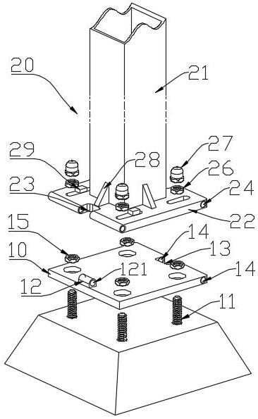
[0050] Such as Figure 1-3 As shown, a light pole includes: a connecting plate 10 and a column 21 .

[0051] Specifically, the connecting plate 10 is connected to the hard ground or platform through a plurality of anchor bolts 11. In this embodiment, there are four anchor bolts 11 arranged in a rectangular shape. One side of the connecting plate 10 is provided with a hinge support 12 , The hinge support 12 is processed with a hinge hole 121, the opposite side of the hinge support 12 is provided with a rectangular groove 13, and the side wall of the rectangular groove 13 is processed with a first socket 14.

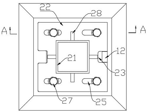
[0052] Specifically, a base plate 22 is provided at the bottom of the column 21, and the base plate 22 has a rectangular structure, wherein any opposite two sides are processed with a rectangular notch 23, and the side wall of the rectangular notch 23 is processed with a through hole 24, and the side where the through hole 24 and the rectangular notch 23 are located Paral...

Embodiment 2

[0060] Such as Figure 4-10 As shown, a method for installing the light pole described in Embodiment 1, the steps are as follows:

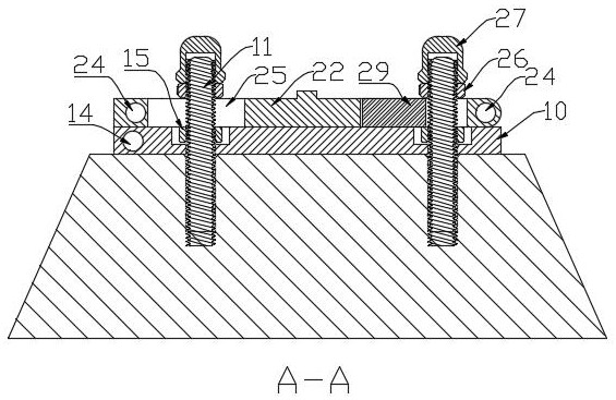
[0061] 1) Fix the anchor bolts 11 on a hard ground or platform. The commonly used methods for fixing the anchor bolts 11 are concrete fixing or welding. When fixing them, the connecting plate 10 needs to be used to position them, and the protrusion of the anchor bolts 11 The length needs to be calculated, and it needs to be greater than the thickness of the connecting plate 10 + the thickness of the bottom plate 22 + the thickness of the locking nut 26, and less than the thickness of the connecting plate 10 + the thickness of the bottom plate 22 + the thickness of the locking nut 26 + the inner hole of the threaded cap 27 depth;

[0062] 2) Install the connecting plate 10 on the anchor bolt 11, and lock it with the fastening nut 15;

[0063] 3) The column 21 is placed horizontally, so that the through hole 24 on either side is placed coaxially w...


PUM


Abstract

The invention provides a lamp post and a mounting method thereof. The lamp post comprises a connecting plate and a stand column. The connecting plate is connected to the hard ground or a platform through a plurality of foundation bolts, a hinge support is arranged on one side of the connecting plate, a hinge hole is machined in the hinge support, a rectangular groove is formed in the opposite sideof the side where the hinge support is located, and a first inserting hole is machined in the side wall of the rectangular groove. A bottom plate is arranged at the bottom of the stand column, the bottom plate is of a rectangular structure, any two opposite sides are provided with rectangular notches; through holes are formed in the side walls of the rectangular notches; the through holes are parallel to the edges where the rectangular notches are located, the hinge support can be embedded in one rectangular notch after installation, the corresponding through holes are coaxial with the hingeholes, strip-shaped holes are machined in the positions, corresponding to the foundation bolts, of the bottom plate, the strip-shaped holes are perpendicular to the axes of the through holes, and thefoundation bolts penetrate through the strip-shaped holes and fasten the bottom plate through locking nuts. The lamp post can be installed by a single person without the help of hoisting equipment, and is simple in structure and convenient to use.

Description

technical field [0001] The invention belongs to the field of public lighting facilities, and in particular relates to a light pole and an installation method thereof. Background technique [0002] Most of the existing light poles are composed of the bottom plate of the column, and are fixed to the ground through the bottom plate. The existing light poles have the following deficiencies: [0003] 1. If it is often necessary to use lifting equipment for hoisting during installation, it is necessary to pay expensive rental fees for lifting equipment, resulting in higher installation costs; [0004] 2. Even if the installation does not use lifting equipment, it needs the cooperation of multiple people to complete the installation, and the installation is not convenient enough; [0005] 3. When repairing the lamps, it is necessary to put the light pole down, or lift the equipment to send the maintenance personnel to the top of the light pole for maintenance. Contents of the in...

Claims


Application Information

Patent Timeline
Patent Type & Authority Applications(China)
IPC IPC(8): F21S8/08F21V21/10E04H12/22E04H12/34
CPCE04H12/2253E04H12/34F21S8/08F21S8/085F21V21/10
Inventor 孙素珍曹代权
Owner 四川嘉灿城市家具科技有限公司
Why Eureka
Try Eureka