High-efficiency arc extinguishing relay

A relay and arc extinguishing technology, which is applied in the direction of relays, electromagnetic relays, electromagnetic relay details, etc., can solve the corrosion of the contact between the moving contact and the static contact, and the arc is easy to hit the inner wall of the insulating cover and rebound to the moving and static contacts , moving reed and other parts, distance reduction and other problems, to achieve the effect of good arc extinguishing effect

Pending Publication Date: 2020-10-09
ZHEJIANG YINGLUOHUA NEW ENERGY TECH CO LTD
View PDF0 Cites 2 Cited by
  • Summary
  • Abstract
  • Description
  • Claims
  • Application Information

AI Technical Summary

Problems solved by technology

[0002] When the moving contact and the static contact of the high-voltage relay are separated, an arc will be generated, and the arc will cause corrosion at the contact point between the moving contact and the static contact, and affect the service life of the moving contact and the static contact
In order to extinguish the arc, a pair of magnetic steel is usually placed on the circumferential outside of the moving and static contacts to blow the arc, but there is still the defect that the arc bounces on the moving and static contacts to reduce the life of the moving and static contacts
The magnetic ste

Method used


Image

  • High-efficiency arc extinguishing relay
  • High-efficiency arc extinguishing relay
  • High-efficiency arc extinguishing relay

Examples


Embodiment 1

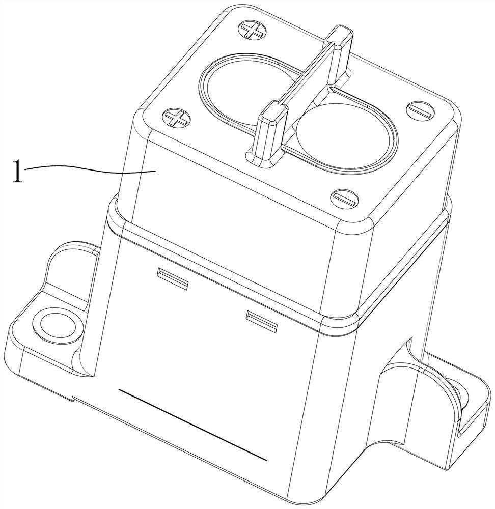
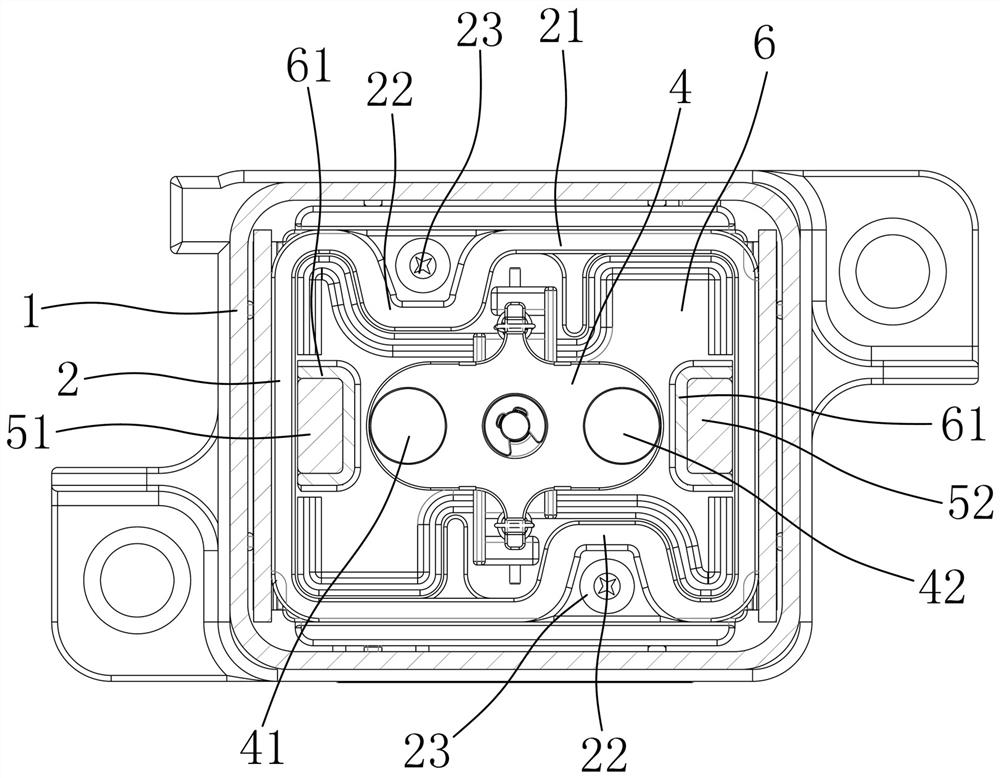
[0028] Depend on figure 1 , figure 2 As shown, a high-efficiency arc-extinguishing relay of the present invention includes an outer shell 1, and an insulating cover 2 and a yoke iron plate are arranged inside the outer shell 1, and the insulating cover 2 and the yoke iron plate 3 are formed to accommodate moving contacts and static contacts. point chamber, the movable contact includes a left movable contact 41 and a right movable contact 42 fixed on the left and right ends of the movable reed 4, and the static contact includes a left static contact corresponding to the left movable contact 41 and a right movable contact. Point 42 corresponds to the right static contact. The magnets used to blow the arc generated by the breaking of the dynamic and static contacts are all arranged in the chamber, the magnets include a first magnet 51 and a second magnet 52, and the first magnet 51 and the second magnet 52 are respectively located in Moving reed 4 left and right sides.

[002...

Embodiment 2

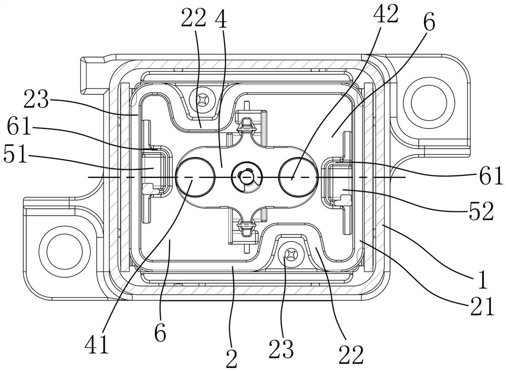
[0033] Depend on figure 1 , image 3 As shown, the difference between this embodiment and the first embodiment is that the axis of the first magnet 51 along the left-right direction and the axis of the second magnet 52 along the left-right direction deviate from the axis of the moving reed 4 along the left-right direction. Wherein, one inner protrusion 22 is located at the left rear of the insulating cover, and the other inner protrusion 22 is located at the right front of the insulating cover, and the first magnetic steel 51 moves to the left inner protrusion to deviate from the axis of the moving reed 4 along the left-right direction. , the second magnetic steel 52 protrudes inwardly and moves to the right to deviate from the axis of the moving reed 4 along the left-right direction.

[0034] In this embodiment, the moving track of the arc close to the inner convex side is longer, so as to improve the arc extinguishing effect.

Embodiment 3

[0036] Depend on figure 1 , Figure 4 As shown, the difference between this embodiment and Embodiment 1 is that the magnets also include a third magnet 53 and a fourth magnet 54, and the third magnet 53 and the fourth magnet 54 are respectively located at the front and rear sides of the moving reed 4 One side of it; the cross-sectional shape of the inner protrusion 22 in embodiment 3 is L-shaped, and the two inner protrusions 22 are located at the opposite corners of the square insulating cover 2 .

[0037] In this embodiment, the insulating cover can be made larger as much as possible while keeping the shape and size of the outer casing of the relay unchanged, so that the distance between the circumferential inner wall of the insulating cover and the dynamic and static contacts is longer, so that the arc will pass through a longer distance. Only when moving can hit the circumferential inner wall of the insulating cover, so as to eliminate the energy of the arc as much as possi...


PUM


Abstract

The invention aims to provide the high-efficiency arc extinguishing relay which is better in arc extinguishing effect and enables an electric arc not to be liable to rebound to a movable contact and astatic contact after the arc hits the inner wall of an insulating cover. In order to achieve the purpose, the invention adopts the following technical scheme that the relay comprises an outer shell,wherein an insulating cover and a yoke plate are arranged in the outer shell; the insulating cover and the yoke plate form a cavity for accommodating a moving contact and a static contact; the movingcontacts comprise a left moving contact and a right moving contact which are fixed at the left end and the right end of the moving reed; the static contacts comprise a left static contact corresponding to the left moving contact and a right static contact corresponding to the right moving contact, and magnetic steel used for arc blowing of electric arcs generated by breaking of the moving contactand the static contact is arranged in the cavity.

Description

technical field [0001] The invention relates to a high-voltage direct current relay, in particular to a high-efficiency arc-extinguishing relay. Background technique [0002] When the moving contact and the static contact of the high-voltage relay are broken, an arc will be generated, and the arc will cause corrosion at the contact between the moving contact and the static contact, and affect the service life of the moving contact and the static contact. In order to extinguish the arc, a pair of magnetic steel is usually placed outside the movable and static contacts for arc blowing, but there is still the defect that the arc bounces on the movable and static contacts to reduce the life of the movable and static contacts. The magnetic steel is placed on the outside of the insulating cover. In the case that the outer body of the relay does not increase, the volume of the insulating cover is made smaller, which is not convenient for the processing and equipment of the insulati...

Claims


Application Information

Patent Timeline
IPC IPC(8): H01H50/38
CPCH01H50/38
Inventor 于荣爱郭顺可陈烜苏朋
Owner ZHEJIANG YINGLUOHUA NEW ENERGY TECH CO LTD
Why Eureka
Try Eureka