
Cupping device and control method thereof

A control method and technology of a cupping device, applied in the fields of medical treatment, health preservation, and physiotherapy, can solve the problems of safety, complicated and laborious operation of the cupping device, and achieve the effect of good experience.

Pending Publication Date: 2020-10-13
TONGJI UNIV
View PDF6 Cites 0 Cited by
  • Summary
  • Abstract
  • Description
  • Claims
  • Application Information

AI Technical Summary

Problems solved by technology

[0005] In view of the above-mentioned shortcomings of the prior art, the purpose of the present invention is to provide a cupping device and its control method, which are used to solve the technical problems of the existing cupping device, which are complicated to operate, laborious, and inconvenient to use by patients, as well as possible problems caused by ignition. safe question

Method used


Image

  • Cupping device and control method thereof

Examples


Embodiment 1

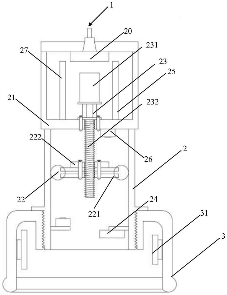
[0039] The present embodiment provides a cupping device, comprising:

[0040] an upper tank, a lower tank connected to the upper tank;

[0041] Wherein, the upper tank body is provided with:

[0042] transmission parts;

[0043] a driving part, mounted on the transmission part, for driving the transmission part to reciprocate in the tank;

[0044] The heating component is arranged in the tank body of the upper tank body and is used to generate heat;

[0045] a control component, electrically connected to the driving component, and used to control the driving component and the heating component according to the environmental information in the tank, so as to adjust the environment in the tank;

[0046] The lower tank body is provided with:

[0047] The sensing part is connected with the control part and is used for sensing the environment information in the tank and transmitting the environment information to the control part.

[0048] The cupping device provided by this e...

Embodiment 2

[0068] This embodiment provides a method for controlling a cupping device, and the method for controlling a cupping device is applied to a mobile terminal. The communication connection between the mobile terminal and the cupping device.

[0069] The control method of described cupping device comprises:

[0070] receiving the first environmental information in the tank from the cupping device, and according to the first environmental information. The first environmental information includes the temperature and / or pressure in the tank sent by the cupping device.

[0071] Feedback the second environmental information matching the user's requirement to the cupping device, so that the cupping device can adjust the environment in its tank according to the second environmental information.

[0072] In this embodiment, the user can set the temperature and / or pressure suitable for himself through the control interface.

[0073] For example, if the temperature is too high, the user c...


PUM


Abstract

The invention provides a cupping device and a control method thereof. The cupping device comprises: an upper cup body; a lower cup body connected to the upper cup body, wherein the upper cup body is internally provided with a transmission part; a driving part which is mounted on the transmission part and used for driving the transmission part to reciprocate in the cup bodies; a heating part whichis arranged in the cup body of the upper cup body and used for generating heat; and a control part which is used for controlling the driving part and the heating part so as to adjust the environment in the cup bodies. A sensing part is arranged in the lower cup body, is connected to the control part and is used for sensing environmental information in the cup bodies and transmitting the environmental information to the control part. According to the cupping device, a piston is driven to vertically move in a threaded transmission mode to change air pressure, and the purpose of accurately controlling the air pressure in the cup bodies is achieved. Therefore, after the air pressure change caused by air leakage is detected, the air pressure can be accurately changed to return to a set value, and a user has a better experience feeling.

Description

technical field [0001] The invention belongs to the fields of health preservation, physical therapy and medical treatment, and relates to a cupping device, in particular to a cupping device and a control method thereof. Background technique [0002] With the development of society, the pressure of people's work and life is gradually increasing, causing most of the staff to maintain a long-term sedentary posture in an air-conditioned environment for a long time, but lack of proper exercise, coupled with bad living habits, such as in the hot summer Drinking a lot of frozen drinks will cause moisture to invade the body. There is an old saying: "Thousands of colds are easy to get rid of, but once wet is hard to get rid of, the wetness is sticky, like oil in the face." The severity and harmfulness of moisture can be seen. The cupping is an effective dehumidification therapy. Cupping therapy is a traditional Chinese medicine therapy in our country. I believe that many people, esp...

Claims


Application Information

Patent Timeline
Patent Type & Authority Applications(China)
IPC IPC(8): A61M1/08A61H9/00A61H39/04A61H39/06A61F7/00
CPCA61F7/007A61H9/0057A61H39/04A61H39/06A61H2201/0207A61M1/08A61M2205/3331A61M2205/3368
Inventor 孙远韬董昊林史新民熊勇虎
Owner TONGJI UNIV
Learn More