Eureka AIR delivers breakthrough ideas for toughest innovation challenges, trusted by R&D personnel around the world.

Closed chest drainage device

A closed, thoracic technology, applied in the direction of suction containers, suction devices, hypodermic injection devices, etc., can solve the problems of detachment of the drainage tube from the drainage bottle, no stabilizing measures, and easy dumping of the drainage bottle, so as to avoid falling off and practical Good performance and anti-dumping effect

Inactive Publication Date: 2017-11-07
周旭
View PDF5 Cites 1 Cited by
  • Summary
  • Abstract
  • Description
  • Claims
  • Application Information

AI Technical Summary

Problems solved by technology

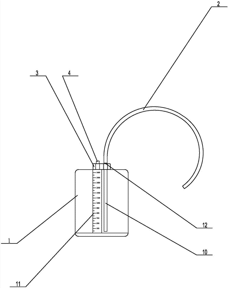
[0003] At present, the structure of the closed chest drainage device is generally as follows: image 3 As shown, it includes a drainage bottle, a drainage tube, a sealing cover is provided between the drainage tube and the drainage bottle, and an exhaust pipe extending into the drainage bottle is provided on the sealing cover. The drainage device with such a structure has the following defects: the patient goes to the toilet or walks When using the drainage bottle, it is difficult to carry the drainage bottle because there is no hand-held measure on the drainage bottle. Patients generally carry the drainage tube directly, and it is very easy for the drainage tube to detach from the drainage bottle, which will affect the treatment of the patient; the bottom of the drainage bottle is a smooth structure , there are no stabilization measures, the stability is poor, and the drainage bottle is prone to tipping due to the displacement of the drainage tube or being touched by people

Method used


Image

  • Closed chest drainage device
  • Closed chest drainage device
  • Closed chest drainage device

Examples


Embodiment Construction

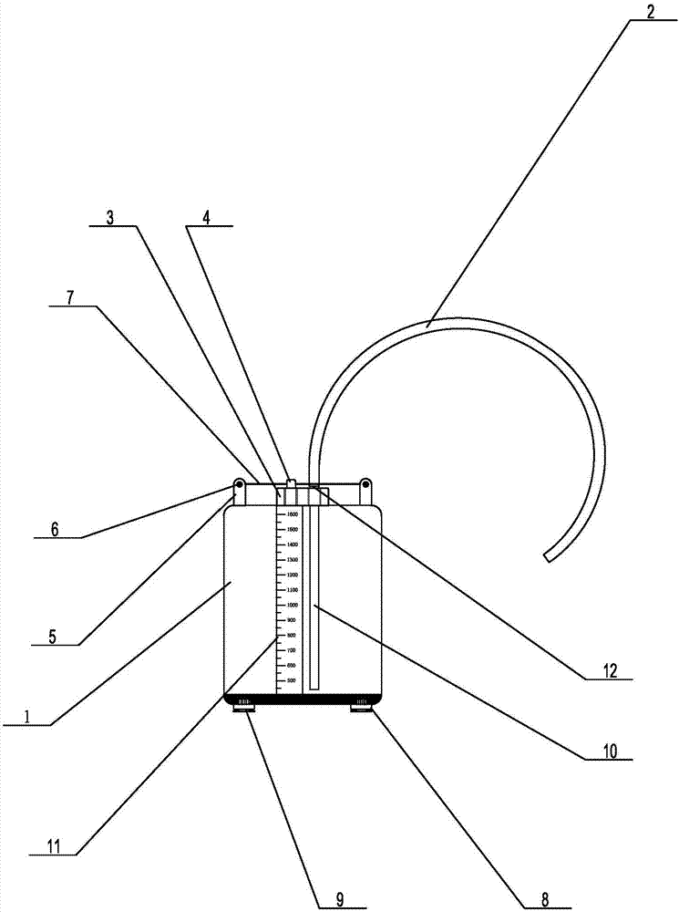
[0018] like figure 1 Propose a kind of specific embodiment of the present invention as shown, chest cavity airtight drainage device, comprise drainage bottle 1, be located at the drainage tube 2 on the drainage bottle, also have the scale gauge 11 that shows liquid volume on the described drainage bottle 1, described A sealing cover 3 is provided between the drainage tube 2 and the drainage bottle 1. In this embodiment, the sealing cover 3 is arranged at the center of the top of the drainage bottle 1. The sealing cover 3 is provided with an exhaust pipe 4 extending into the drainage bottle 1. The sealing cover is also provided with a drainage tube joint 12, the bottom end of the drainage tube 2 is nested outside the drainage tube joint 12, and the end of the drainage tube joint 12 is connected with the receiving tube 10 in the drainage bottle 1. connection; both sides of the top of the drainage bottle 1 are provided with a bobbin support seat 5, and a bobbin 6 is arranged on ...


PUM


Abstract

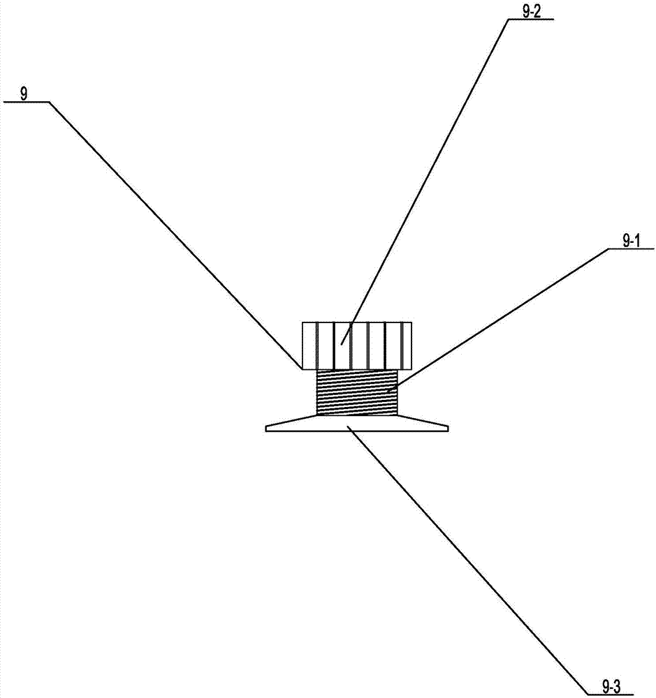
The invention provides a closed chest drainage device comprising a drainage bottle and a drainage tube. A sealing cap is arranged between the drainage tube and the drainage bottle, an exhaust tube is arranged on the sealing cap, a bobbin support seat is arranged on each side of the top end of the drainage bottle, a bobbin is arranged on each bobbin support seat, and a rope handle is connected between the bobbins. A plurality of fixing support seats are arranged at the bottom end of the drainage tube, a fixing component is arranged on each fixing support seat, each fixing component comprises a threaded hole formed in the corresponding fixing support seat, a threaded rod is sleeved in the threaded hole, and the top end of each threaded rod is provided with a clamp adjusting nut while the bottom end is provided with a sucker. The drainage device is provided with the rope handle, so that convenience is brought to patients to carry the drainage bottle under any circumstances, and danger that the drainage tube falls off is avoided effectively; the bottom end of the drainage bottle is provided with the fixing components, so that the drainage tube can be effectively prevented from toppling over by adjusting the length of the threaded rod and changing the air pressure of the suckers, and safety performance is good.

Description

technical field [0001] The invention relates to a medical device, in particular to a closed chest drainage device. Background technique [0002] Closed chest drainage is a common clinical operation in thoracic surgery, and it is an effective method for treating empyema, traumatic hemothorax, pneumothorax, and spontaneous pneumothorax. Under normal circumstances, the human thoracic cavity is in a negative pressure state, but when the chest wall is damaged due to surgery, trauma, etc., or long-term lung diseases such as tuberculosis, emphysema, bronchiectasis and other diseases lead to the rupture of the alveoli at the edge of the lung, air can enter the thoracic cavity , so that the negative pressure in the chest cavity disappears, and the lungs will lose their breathing function due to the pressure becoming smaller. Therefore, a closed chest drainage technique is needed to drain the air and fluid in the chest cavity. The chest drainage device generally uses a method of pla...

Claims


Application Information

Patent Timeline
Patent Type & Authority Applications(China)
IPC IPC(8): A61M1/00
CPCA61M1/0001A61M1/0023A61M2202/04A61M2210/101A61M1/84A61M2202/0014
Inventor 周旭
Owner 周旭
Why Eureka
Eureka Blog
Learn More