Plug-in mounting power assisting device with locking function

A technology of booster and plug-in, which is applied to fixtures, mechanical equipment, etc., can solve the problems of panel space occupation of components and affect the appearance of components, and achieve the effects of quick plug-in operation, labor-saving booster operation, and simple operation.

Active Publication Date: 2020-10-13
THE 724TH RES INST OF CHINA SHIPBUILDING IND
View PDF6 Cites 0 Cited by
  • Summary
  • Abstract
  • Description
  • Claims
  • Application Information

AI Technical Summary

Problems solved by technology

[0004] The purpose of the present invention is to provide a plug-in booster device with a locking function to solve the problem that the existing booster locker occupies the space of the component panel and affects the aesthetics of the component

Method used


Image

  • Plug-in mounting power assisting device with locking function
  • Plug-in mounting power assisting device with locking function
  • Plug-in mounting power assisting device with locking function

Examples


Embodiment Construction

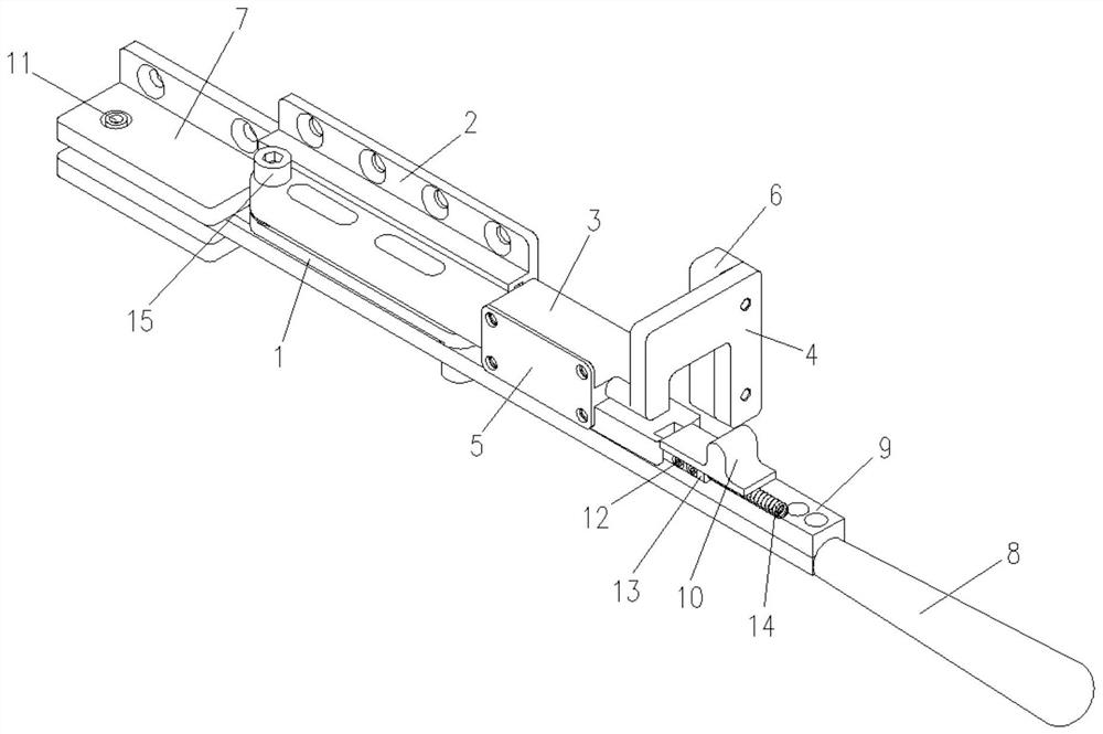
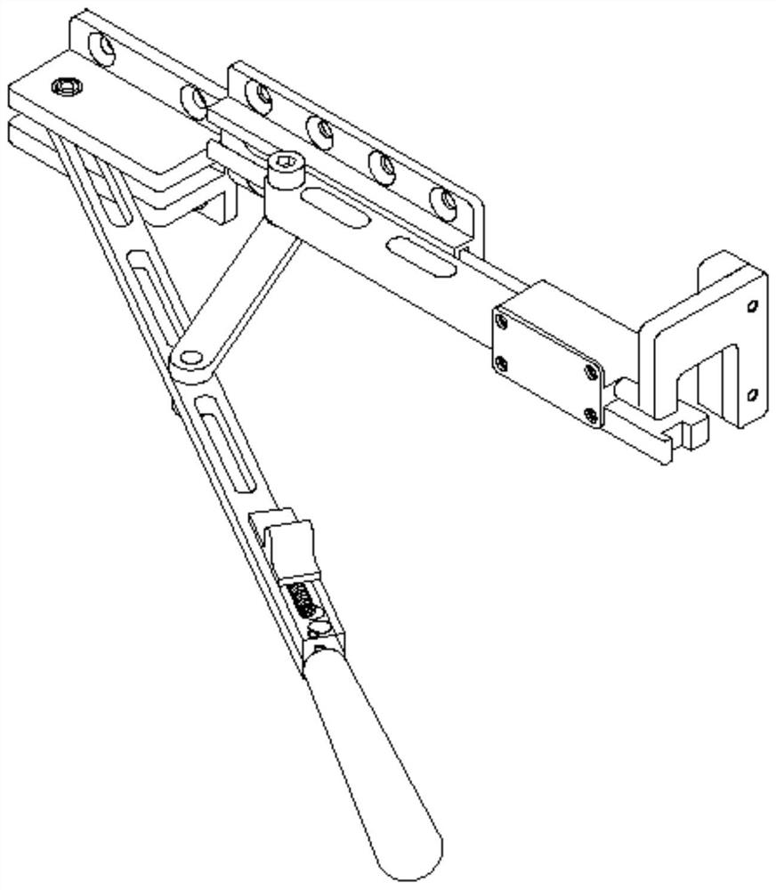
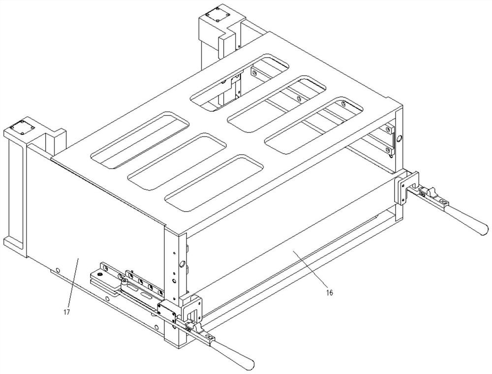
[0012] The specific implementation manners of the present invention will be described in detail below in conjunction with the accompanying drawings.

[0013] combine Figure 1-Figure 3 , a locking mechanism with a booster function, including a connecting rod 1, a guide rail 2, a slide bar 3, a handle 8 and a base 7, and the handle 8 includes a lock cap 9, a shift block 10, a latch 12, a lock hook 13 and a push spring 14. The slide bar 3 includes a pressing piece 4, a cover plate 5 and a backing plate 6. The handle 8 and the base 7 are riveted through the bolt 11 to form a rotating pair. The lock hook 13 presses the push spring 14 into the lock cap 9, pushing To a certain position, the shifting block 10 is inserted into the lock hook 13 through the waist-shaped hole on the upper end surface of the lock cap 9, riveted with the latch 12, and the push spring 14 is always kept in a compressed state, and the pressing part 4 is inserted into the semicircular guide of the slide bar 3....


PUM


Abstract

The invention relates to a plug-in mounting power assisting device with a locking function. The device comprises a linear limiting mechanism, a connecting rod and a power assisting locking mechanism which are connected through guide fasteners. The linear limiting mechanism comprises a guide rail, a sliding rod, a pressing piece, a cover plate and a base plate; an I-shaped guide groove is formed inthe guide rail; one side of the sliding rod and the guide rail are mounted in a matched mode through the guide groove; a pressing piece mounting cavity is designed in the other side of the sliding rod; the pressing piece is mounted in the cavity and then is sealed through the cover plate and the fasteners; a large-diameter cylinder on the pressing piece limits axial movement of the pressing piece, and a small-diameter cylinder guarantees that the pressing piece can rotate freely; the power assisting locking mechanism comprises a base, a handle, a lock cap, a shifting block, a plug pin, a lockhook and a pushing and pressing spring; the handle and the base are riveted through the plug pin, and the handle can rotate freely around the base; the pushing and pressing spring is mounted betweenthe lock hook and the lock cap in an abutting mode and pushes and presses the lock hook forwards; and the plug-in mounting power assisting device cannot occupy the space of an assembly panel, the armof force is large, operation is convenient, and labor is saved.

Description

technical field [0001] The invention belongs to the field of electronic systems. Background technique [0002] At present, radar liquid cooling components mostly adopt the blind insertion form, including water blind insertion and electric blind insertion. The blind insertion force between the blind water plug and the blind water socket used in water blind insertion is very large, resulting in the insertion of liquid cooling components. The process of getting into the box is very laborious. In practical engineering applications, when the liquid-cooled components are inserted and installed, two people usually cooperate to install them. One of them presses the liquid-cooled components, and the other tightens the captive screws at both ends. It is extremely inconvenient to install and operate in the limited space on site. [0003] In order to solve this problem, there are already many booster locks. The commonly used booster locks are to install the main body of the handle on t...

Claims


Application Information

Patent Timeline
Patent Type & Authority Applications(China)
IPC IPC(8): F16B1/04
CPCF16B1/04
Inventor 李谦项立银李高杰晏腾飞
Owner THE 724TH RES INST OF CHINA SHIPBUILDING IND
Why Eureka
Try Eureka