
Multi-intersection signal timing system and method in network connection traffic environment

A technology of signal timing and multi-intersection, applied in the field of multi-intersection signal timing system, can solve the problems of inability to realize multi-intersection refined traffic coordination control, difficult to fully adapt, and limited optimization space.

Active Publication Date: 2020-10-13
TONGJI UNIV
View PDF7 Cites 10 Cited by
  • Summary
  • Abstract
  • Description
  • Claims
  • Application Information

AI Technical Summary

Problems solved by technology

[0004] The above-mentioned traditional signal timing method is limited by traffic perception conditions, and the data sources based on it only include historical traffic conditions and aggregated traffic demand information (such as traffic flow, density, queuing, etc.) detected by fixed detectors. Disaggregated information for perception and prediction
Therefore, the signal timing is greatly limited by the existing phase combination and phase sequence framework, the optimization space is limited, it is difficult to fully adapt to the dynamically changing traffic demand, it is impossible to realize the refined traffic coordination control of multiple intersections, and it is easy to increase vehicle traffic delays , reduce the traffic efficiency of the road network

Method used


Image

  • Multi-intersection signal timing system and method in network connection traffic environment
  • Multi-intersection signal timing system and method in network connection traffic environment
  • Multi-intersection signal timing system and method in network connection traffic environment

Examples


Embodiment

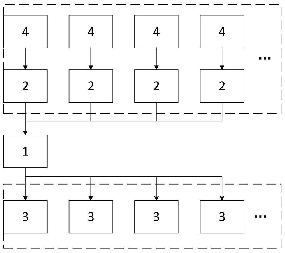
[0065] Such as figure 1 As shown, a multi-intersection signal timing system in a networked traffic environment includes a traffic control center 1, a roadside unit 2 and an intersection signal 3. The input terminal of the traffic control center 1 communicates with the roadside unit 2 through The on-board sensors 4 on the vehicles in the network are connected, and the output terminal of the traffic control center 1 is connected to the intersection signal 3. The specific working process of the system is: the networked vehicles perceive the real-time vehicle status, including the current position, through the on-board sensors 4 and speed, and send the real-time status and future path plan of the vehicle to the roadside unit 2, and then to the traffic control center 1;

[0066] The traffic control center 1 calculates and solves the corresponding signal timing scheme according to the collected vehicle status and future path;

[0067] The traffic control center 1 sends the calculat...


PUM


Abstract

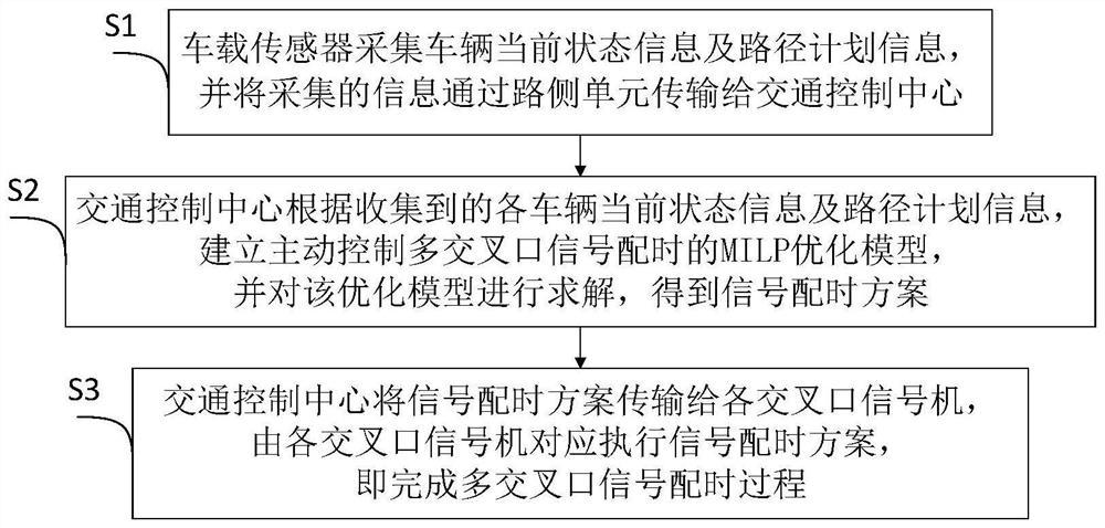
The invention relates to a multi-intersection signal timing system and method in a network connection traffic environment, and the method comprises the steps that a vehicle-mounted sensor collects thecurrent state information and path planning information of a vehicle, and transmits the collected information to a traffic control center through a road side unit; the traffic control center establishes an MILP optimization model for actively controlling multi-intersection signal timing according to the collected current state information and path planning information of each vehicle, and solvesthe optimization model to obtain a signal timing scheme; and the traffic control center transmits the signal timing scheme to each intersection annunciator, and each intersection annunciator correspondingly executes the signal timing scheme, so that the multi-intersection signal timing process is completed. Compared with the prior art, evolution of the current state and the future state of the individual level of the vehicle is considered, the method is not limited to fixed phase combination and phase sequence, multi-intersection signal timing precision cooperation can be achieved, and vehiclepassing delay is reduced.

Description

technical field [0001] The invention relates to the technical field of intelligent traffic control, in particular to a multi-intersection signal timing system and a method thereof in a networked traffic environment. Background technique [0002] The urban road network carries the traffic demand of vehicles that change dynamically in time and space. Intersection signals are the key control means for allocating traffic flow rights in different directions at intersections. Signal timing (time ratio of red and green lights at intersections) directly determines The utilization efficiency of road resources directly affects the safety and efficiency of people's travel. The optimization of signal timing is mainly reflected in two levels: the adaptive optimization of dynamic demand at the level of single intersection, and the coordinated optimization of signals at the level of multiple intersections. [0003] The existing timing methods for single intersections are mostly based on t...

Claims


Application Information

Patent Timeline
IPC IPC(8): G08G1/081G08G1/083G08G1/01G08G1/095G06N7/00
CPCG08G1/081G08G1/083G08G1/0116G08G1/012G08G1/095G06N7/00
Inventor 马成元杨晓光俞春辉龙可可
Owner TONGJI UNIV
Learn More