Tunnel grounding intelligent method and device

A tunnel and grounding body technology, applied in the direction of circuit devices, emergency protection circuit devices, emergency protection devices with automatic disconnection, etc., can solve problems such as accelerated insulation aging, poor ventilation, and reduced insulation of power cables, and achieve dynamic protection Effect

Pending Publication Date: 2020-10-13
中冶南方城市建设工程技术有限公司 +1
View PDF2 Cites 0 Cited by
  • Summary
  • Abstract
  • Description
  • Claims
  • Application Information

AI Technical Summary

Problems solved by technology

[0003] Power cables are buried underground all year round, and the surrounding environment is complex, which brings some hidden dangers to the safe operation of power cables. Although tunnels can solve some problems of buried cables, due to the complex operating environment of tunnels, it is easy to cause water accumulation, Phenomena such as humidity and poor ventilation will reduce the insulation of the power cable and even cause damage. Therefore, the failure rate of the power cable is always relatively high and may cause damage to personnel
When the power cable is in normal operation, the alternating magnetic field generated by the cable core current will generate an induced voltage on the metal sheath. In order to ensure the safe operation of the power cable, at least one end of the cable metal sheath is required to be grounded. According to regulations, single-core cable metal The sheath grounding circulation current is generally not greater than 10% of the load current. If the circulation current exceeds the assembly, it will cause loss and heat generation, which will cause local heating of the cable to affect the current carrying capacity, accelerate insulation aging, and cause the temperature of the lead contact or welding point to rise locally due to possible poor connection. , endanger the safe operation of the cable line and may cause injury to personnel

Method used


Image

  • Tunnel grounding intelligent method and device
  • Tunnel grounding intelligent method and device
  • Tunnel grounding intelligent method and device

Examples


Embodiment Construction

[0030] The present invention will be further described below in conjunction with specific examples and accompanying drawings.

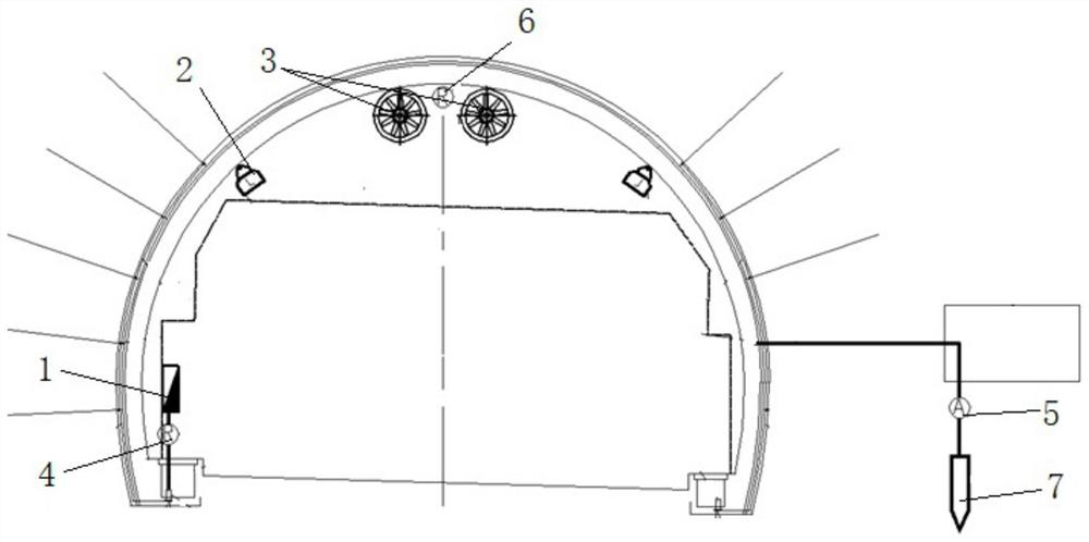
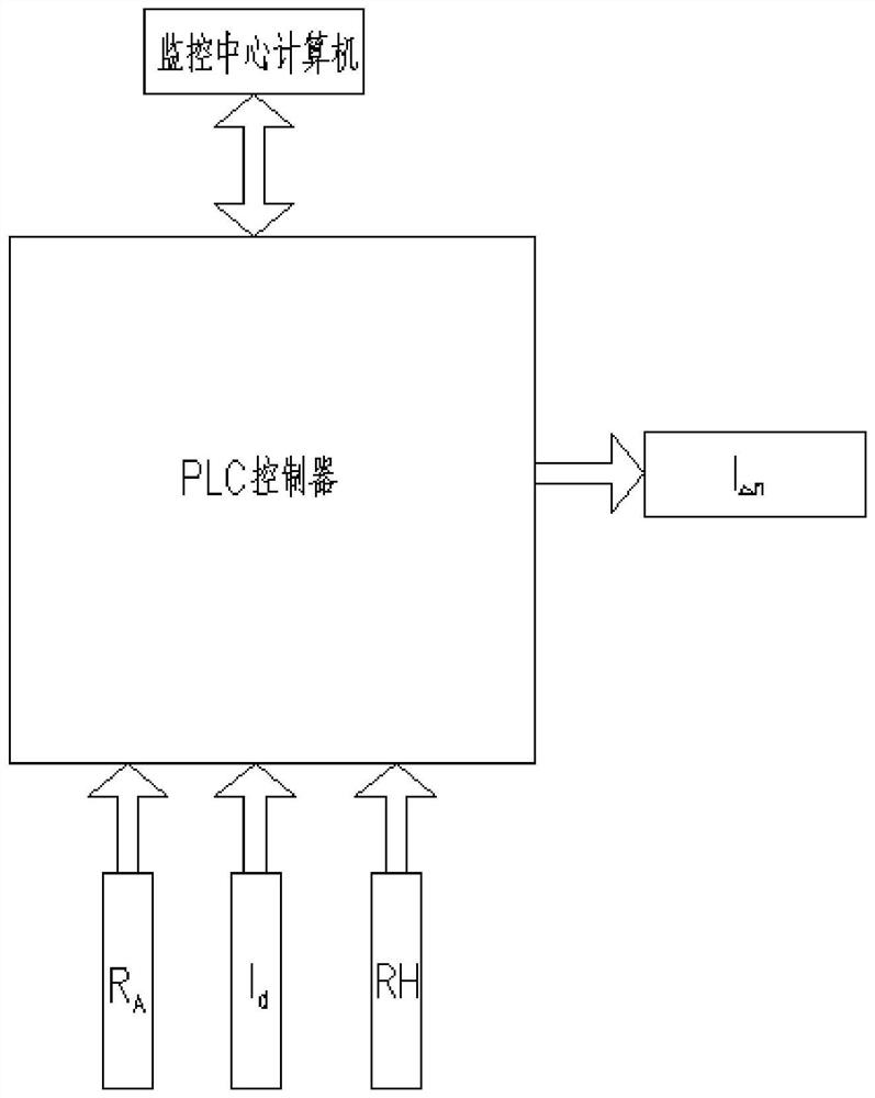
[0031] For the convenience of analysis, the symbols are defined as follows: I Δn is the operating current value of the residual current protector in the tunnel distribution box, in A; R A It is the resistance value measured by the ground resistance measuring instrument, the unit is Ω; I d It is the current value measured by the ground current measuring instrument, and the unit is A; RH is the relative humidity measured by the relative humidity measuring instrument, and the unit is %.

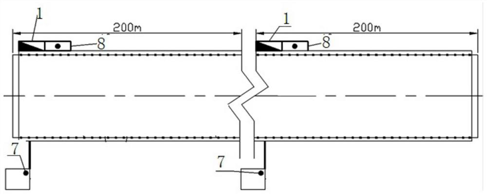
[0032] The invention provides a tunnel grounding intelligent device, such as Figure 1 to Figure 3 As shown, the tunnel is divided into a section according to a certain distance, and a set of this device is installed in each section, and the certain distance described in this embodiment is 200m. The device includes a tunnel distribution box 1, a control box 8, a sens...


PUM


Abstract

The invention provides a tunnel grounding intelligent method and device, and the method comprises the steps: dividing a tunnel according to a certain distance, setting a tunnel distribution box in each section, setting a residual current protector with an adjustable residual action current value in each tunnel distribution box, and enabling each tunnel distribution box to supply power to an illumination lamp and a jet fan in the corresponding section; wherein each section is provided with a deeply-buried grounding body and a control box, and the deeply-buried grounding bodies between the sections are mutually independent; acquiring the resistance to ground, the current to ground and the relative humidity in the interval in real time; and when the deeply-buried grounding body is slowly corroded with the passage of time and the resistance value is increased, the control box modifying the residual action current value of the residual current protector on line, so that dynamic protection of tunnel grounding is realized.

Description

technical field [0001] The invention belongs to the technical field of intelligent tunnel grounding, and in particular relates to an intelligent method and device for tunnel grounding. Background technique [0002] Power cables play a very important role in my country's infrastructure. With the development of my country's power industry, power cables have replaced traditional overhead lines. Compared with traditional overhead lines, power cables have huge advantages, not only saving space , It can also prevent safety hazards caused by bad weather. [0003] Power cables are buried underground all year round, and the surrounding environment is complex, which brings some hidden dangers to the safe operation of power cables. Although tunnels can solve some problems of buried cables, due to the complex operating environment of tunnels, it is easy to cause water accumulation, Phenomena such as moisture and poor ventilation will reduce the insulation of the power cable and even cau...

Claims


Application Information

Patent Timeline
IPC IPC(8): H02H3/00H02H3/16H02H3/32
CPCH02H3/006H02H3/16H02H3/32
Inventor 张号军赵昊裔邵义安李海峰
Owner 中冶南方城市建设工程技术有限公司
Why Eureka
Try Eureka