
Method for correcting position of photosensitive element

A photosensitive element and light source technology, which is applied in the direction of electrical components, color TV parts, TV system parts, etc., can solve the problems of complicated operation and difficult to find photosensitive elements, and achieve the effect of simple operation and high precision

Active Publication Date: 2020-10-13
O FILM IMAGE TECH (GUANGZHOU) CO LTD
View PDF6 Cites 2 Cited by
  • Summary
  • Abstract
  • Description
  • Claims
  • Application Information

AI Technical Summary

Problems solved by technology

The current technology is not easy to find the position where the center of the photosensitive element intersects the optical axis, and at least 5 defocus curves need to be output when adjusting the photosensitive element to be perpendicular to the optical axis of the lens, and each defocus curve needs to move the photosensitive element, which is complicated to operate

Method used


Image

  • Method for correcting position of photosensitive element
  • Method for correcting position of photosensitive element
  • Method for correcting position of photosensitive element

Examples


Embodiment Construction

[0041] The technical solutions in the embodiments of the present invention will be clearly and completely described below in conjunction with the accompanying drawings in the embodiments of the present invention. Obviously, the described embodiments are only part of the embodiments of the present invention, not all of them. Based on the implementation manners in the present invention, all other implementation manners obtained by persons of ordinary skill in the art without making creative efforts belong to the scope of protection of the present invention.

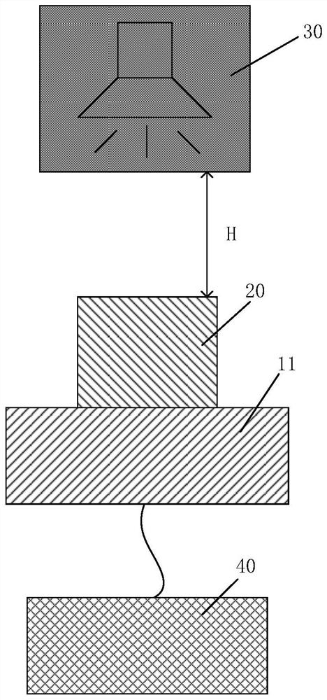
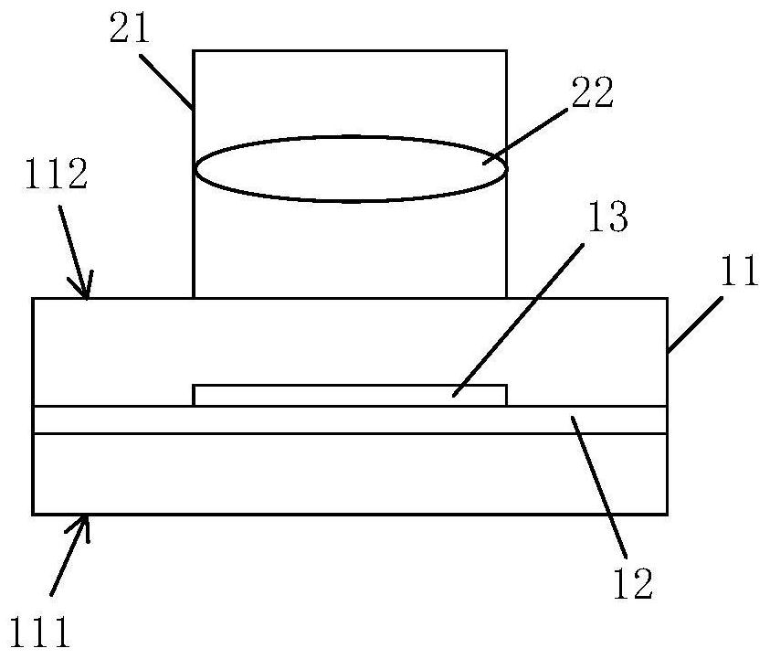
[0042] Please refer to figure 1 , The device for correcting the position of the photosensitive element provided by the embodiment of the present invention includes a light source 30 and a controller 40 . The light source 30 is used to emit light to the camera module. The camera module includes a bracket 11 and a lens 20 . The controller 40 is electrically connected to the camera module.

[0043] In this embodiment, the lig...


PUM


Abstract

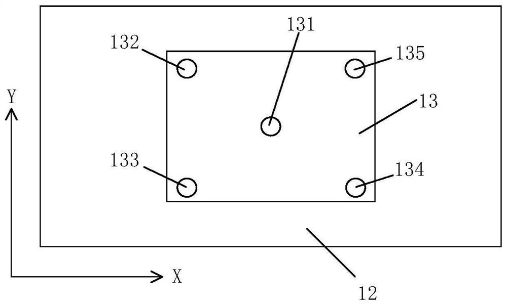
The invention provides a method for correcting the position of a photosensitive element, and the photosensitive element is disposed on a substrate of a camera module group, and the method comprises the steps: enabling a light source to be aligned with a lens, and enabling light emitted by the light source to irradiate the photosensitive element through the lens; moving the photosensitive element on the substrate to enable the light intensity value of the central feature point of the photosensitive element to be a critical value, and enabling the central feature point to intersect with the optical axis of the lens; and adjusting the photosensitive element so that the light intensity values of the multiple feature points on the photosensitive element are enabled to be greater than or equal to the preset light intensity value, wherein the preset light intensity value is the light intensity value measured when the photosensitive element is aligned with the position of the lens. Through adoption of the method provided by the invention, the position correction of the photosensitive element is realized, so that the optimal imaging position of the lens and the photosensitive element is found, and the operation is simple.

Description

technical field [0001] The invention belongs to the technical field of camera modules, in particular to a method for correcting the position of a photosensitive element. Background technique [0002] The camera module includes a lens and a photosensitive element. The position calibration of the photosensitive element and the lens, that is, the photosensitive element is perpendicular to the optical axis of the lens, and the center of the photosensitive element intersects the optical axis, is usually called the leveling of the photosensitive element (adjusting the level of the photosensitive element). [0003] The leveling of the photosensitive element and finding the best imaging position have a crucial impact on the imaging effect. If the photosensitive element cannot be leveled or is not in the best position for imaging, the final imaged photo may have defects such as distortion and missing part of the image . [0004] The leveling of the photosensitive element and the ac...

Claims


Application Information

Patent Timeline
Patent Type & Authority Applications(China)
IPC IPC(8): H04N17/00H04N5/225
CPCH04N17/002H04N23/54H04N23/55
Inventor 胡伟鹏孙昭源胡昌昌高洪明
Owner O FILM IMAGE TECH (GUANGZHOU) CO LTD
Learn More