Hammer combination device

A combined device and hammer technology, applied in metal processing, metal processing equipment, manufacturing tools, etc., can solve the problems of manpower consumption, cumbersome operation process, affecting work efficiency, etc., and achieve the effect of saving manpower and simple operation

Active Publication Date: 2020-10-16
NANJING HANXIYUE AUTOMATION TECH CO LTD
View PDF14 Cites 7 Cited by
  • Summary
  • Abstract
  • Description
  • Claims
  • Application Information

AI Technical Summary

Problems solved by technology

[0006] In order to overcome the disadvantages that the operation process of the above method is cumbersome, the operation is relatively labor-intensive, and the hammer handle and the hammer head are prone to displacement during operation, thereby affecting the work efficiency, the technical problem to be solved by the present invention is to provide a A hammer combination device that can save manpower and fix the hammer head and hammer handle to improve work efficiency

Method used


Image

  • Hammer combination device
  • Hammer combination device
  • Hammer combination device

Examples


Embodiment 1

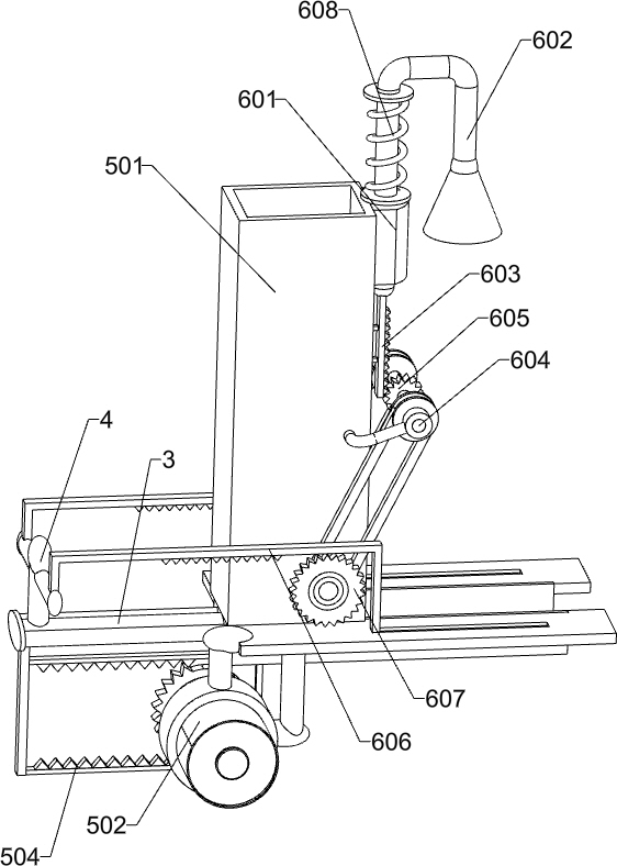
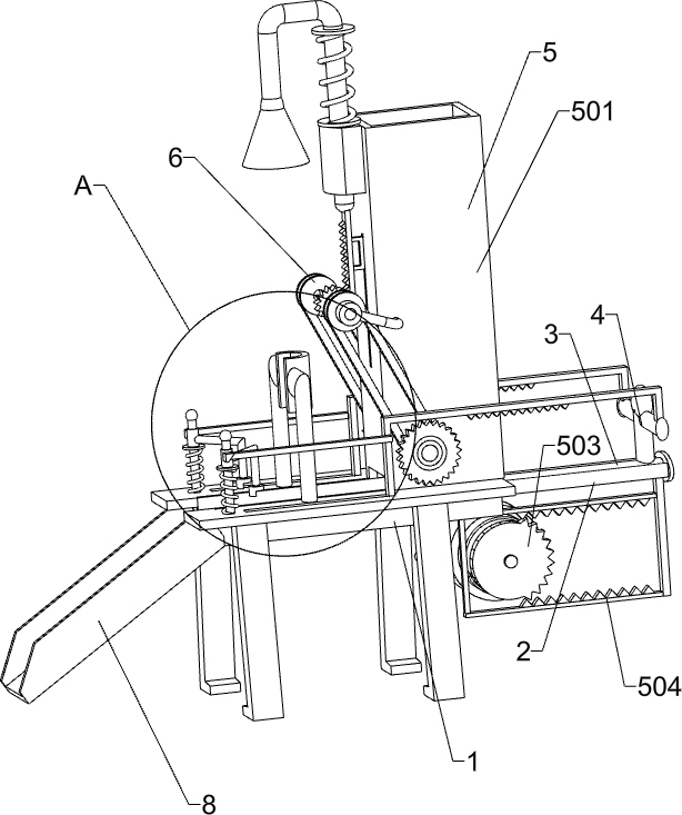
[0023] A hammer combination device such as Figure 1-2 As shown, it includes a grooved plate 1, a guide frame 2, a push rod 3 and a connecting rod 4, the right side of the groove plate 1 is connected with a guide frame 2, the guide frame 2 is slidably connected with a push rod 3, and the top of the push rod 3 Connected with connecting rod 4, also includes unloading mechanism 5 and down-pressing mechanism 6, is provided with unloading mechanism 5 between groove plate 1 and push rod 3, and unloading mechanism 5 is provided with down-pressing mechanism 6.

[0024] The blanking mechanism 5 includes a material frame 501, a reduction motor 502, a sector gear 503 and a back-shaped rack 504. The right side of the groove plate 1 top is connected with the material frame 501, and the bottom right side of the groove plate 1 is equipped with a reduction motor 502. The reduction motor The output shaft of 502 is connected with a sector gear 503 , and the bottom of the push rod 3 is connected...

Embodiment 2

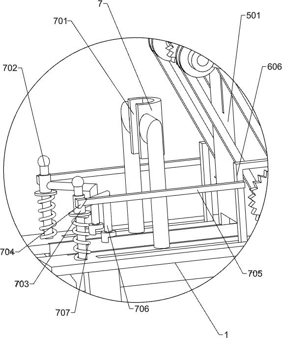
[0028] On the basis of Example 1, such as figure 1 and image 3 As shown, a stabilizing mechanism 7 is also included, and the stabilizing mechanism 7 includes an arc-shaped ferrule 701, a guide rod 702, a sleeve 703, a wedge block 704, an extruding rod 705, an L-shaped limit rod 706 and a pressure spring 707. The left side of the top of the groove plate 1 is connected with an arc-shaped ferrule 701, and the front and rear sides of the groove plate 1 on the left side of the arc-shaped ferrule 701 are connected with guide rods 702, and the guide rod 702 is slidably connected with a sleeve 703. 703 is connected with a wedge-shaped block 704, and the drive rack 606 is connected with an extruding rod 705. The extruding rod 705 cooperates with the wedge-shaped block 704. The right side of the sleeve 703 is connected with an L-shaped stop rod 706. The sleeve 703 and the groove A pressure spring 707 is connected between the plates 1 , and the pressure spring 707 is sleeved on the gui...


PUM


Abstract

The invention relates to a combination device, in particular to a hammer combination device. The technical problem that how to design a hammer combination device that can save manpower during operation and fix a hammer head and a hammer handle, thereby improving work efficiency is solved. The hammer combination device includes a groove plate, a connecting rod, a feeding mechanism and a pressing mechanism; one side of the groove plate is connected with a guide frame, and a push rod is slidably connected to the guide frame; the connecting rod is connected to the top of the push rod; the feedingmechanism is arranged between the groove plate and the push rod; and the pressing mechanism is arranged on the feeding mechanism. Hammers are combined through the coordinated operation of the feedingmechanism and the pressing mechanism, thereby achieving the effect of combining the hammers.

Description

technical field [0001] The invention relates to a combination device, in particular to a hammer combination device. Background technique [0002] A hammer is a tool for striking an object to move or deform it. Most commonly used for hammering nails, straightening or knocking objects open. Hammers come in a variety of forms, the most common being a handle and top. One side of the top is flat for striking, and the other side is the hammer head. A hammer is usually divided into a hammer head and a hammer handle during production, and the hammer head and the hammer handle need to be combined to form a hammer after the production is completed. [0003] At present, the method of combining the hammer head and the hammer handle is usually to manually insert the hammer handle into the hammer head, and then knock the hammer handle to knock the hammer handle into the hammer head. Manpower is required, and the hammer head and hammer handle cannot be positioned during operation, and ...

Claims


Application Information

Patent Timeline
Patent Type & Authority Applications(China)
IPC IPC(8): B23P19/00B23P19/02B23P19/12
CPCB23P19/02B23P19/12B23P19/006B23P19/001
Inventor 胡嘉强
Owner NANJING HANXIYUE AUTOMATION TECH CO LTD
Why Eureka
Try Eureka