Fiber-optic gyroscope with on-line fault self-checking function
A fiber optic gyroscope, fault self-checking technology, applied in Sagnac effect gyroscopes, gyroscopes/steering sensing equipment, measuring devices and other directions, can solve the problem of not being able to guarantee the fiber optic gyroscope, not being able to automatically alarm and work normally, etc. , to achieve the effect of realizing online working status self-check, reducing the risk of adverse effects, and being easy to implement
- Summary
- Abstract
- Description
- Claims
- Application Information
AI Technical Summary
Problems solved by technology
Method used
Image

Examples
Embodiment Construction
[0025] In order to make the object, technical solution and advantages of the present invention clearer, the present invention will be further described in detail below in conjunction with the accompanying drawings and embodiments. It should be understood that the specific embodiments described here are only used to explain the present invention, not to limit the present invention.
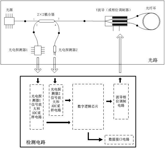
[0026] In the embodiment of the present invention, the fiber optic gyroscope with online fault self-checking function includes two parts: the optical path and the detection circuit, such as figure 1 shown. The optical path part includes light source, 2×2 coupler, Y waveguide, fiber ring, photodetector 1, and photodetector 2. Photodetector 1 is used to detect Sagnac interference light signal, and photodetector 2 is used to detect the output light of the light source. Signal. The output pigtail of the light source is connected to the 1-port pigtail of the 2×2 coupler, the 2-port pigtail of the 2×2 ...
PUM
 Abstract
Description
Claims
Application Information
 - R&D
- Intellectual Property
- Life Sciences
- Materials
- Tech Scout
- Unparalleled Data Quality
- Higher Quality Content
- 60% Fewer Hallucinations
Browse by: Latest US Patents, China's latest patents, Technical Efficacy Thesaurus, Application Domain, Technology Topic, Popular Technical Reports.
© 2025 PatSnap. All rights reserved.Legal|Privacy policy|Modern Slavery Act Transparency Statement|Sitemap|About US| Contact US: help@patsnap.com