
Three-dimensional image display device and three-dimensional image display method

A technology of a display device and a display method, which can be applied to stereo systems, stereo photography, image communication, etc., can solve the problems of complex structure, space and time constraints, and increase in the total area of ​​the image reproduction panel configuration, and achieve less distortion, The effect of increasing light density

Active Publication Date: 2020-10-16
ASUKANET
View PDF8 Cites 0 Cited by
  • Summary
  • Abstract
  • Description
  • Claims
  • Application Information

AI Technical Summary

Problems solved by technology

[0006] Therefore, in the stereoscopic image display device described in Patent Document 1, the structure is complicated, and the rear side of the display control panel is enlarged. In the three-dimensional image display device described in Patent Document 2, the rear side of the image display panel is enlarged. and the problem that the total arrangement area of ​​the image reproduction panel (the total vertical and horizontal dimensions of a plurality of image reproduction panels) increases
Therefore, for the use (utilization) of the device, there is a problem that constraints arise in terms of place and time.

Method used


Image

  • Three-dimensional image display device and three-dimensional image display method
  • Three-dimensional image display device and three-dimensional image display method
  • Three-dimensional image display device and three-dimensional image display method

Examples


Embodiment Construction

[0050] Next, an embodiment embodying the present invention will be described with reference to the drawings in order to understand the present invention.

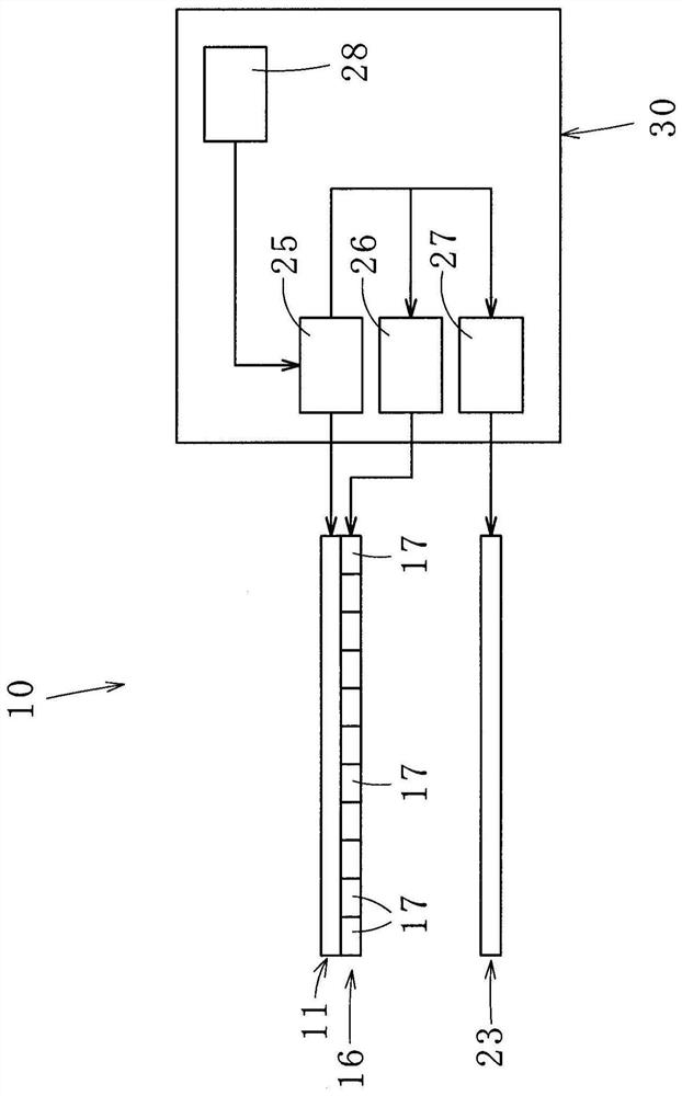
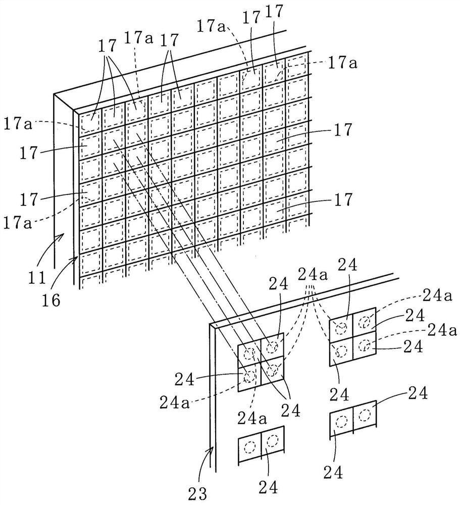
[0051] Figure 1 ~ Figure 6 The illustrated stereoscopic image display device 10 according to an embodiment of the present invention condenses light output from a plurality of small images 12a to 12d displayed on the display 11 to form a three-dimensional image (stereoscopic image).

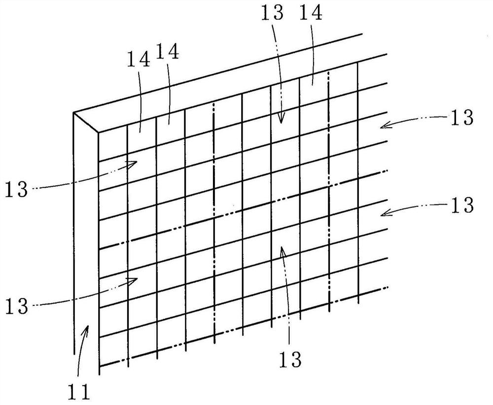
[0052] First, like figure 2 As shown, the display surface of the display 11 is divided into a plurality of segments 13. In this embodiment, an area of ​​4×4 pixels in the vertical and horizontal directions is set as one segment 13, but the number of pixels constituting one segment can be appropriately selected. In addition, the section 13 here represents an area on the display in the display 11, and does not mean that the display 11 is physically divided. And, as Figure 4 , Figure 5 As shown, small images 12a-12d having a plurality of (here, fo...


PUM


Abstract

Provided according to the present invention is a three-dimensional display device comprising: a display (11) in which small images (12a to 12d) each including a plurality of micro-images (14) are displayed in respective sections into which the display is divided; a shutter panel (16) including first mechanical shutters (17) arranged in units of the micro-images (14) and turned on and off in unitsof the micro-images (14) to operate each section in association with the corresponding small image (12a to 12d) in a time-division manner, the shutter panel (16) being disposed in front of the display(11); and an image forming panel (23) in which image forming means (24) are arranged in juxtaposition for forming, into an image, light traveling from the small images (12a to 12d) when the first mechanical shutters (17) are turned on. Each of the small images (12a to 12d) forms a part of a three-dimensional image, the image forming means (24) is provided for each of the small images (12a to 12d), each of the small images (12a to 12d) includes a plurality of micro-images (14) distributively arranged, and each of the image forming means (24) is located on an axis extending through a central area of the corresponding small image (12a to 12d).

Description

Technical field [0001] The present invention relates to a stereoscopic image display device and a stereoscopic image display method, capable of viewing high-resolution stereoscopic images (including two-dimensional images) with the same feeling as daily life without using special glasses. Background technique [0002] Conventionally, among various stereoscopic image display methods, an ideal stereoscopic image display method is an aerial image reproduction method that uses data (image) recording an optical aerial image of an object to form a stereoscopic image in space. [0003] Here, the principle of the aerial image reproduction method will be explained. Such as Picture 10 As shown, the light shielding plate 51 is arranged at a predetermined interval in front of the three-dimensional object (object) 50. A plurality of (here, three) pin holes 52a to 52c are formed in the light shielding plate 51. In addition, a photosensitive film 53 is arranged in parallel with the light-shield...

Claims


Application Information

Patent Timeline
Patent Type & Authority Applications(China)
IPC IPC(8): G03B35/16G02B30/00H04N13/302H04N13/354
CPCG02B30/24G02B30/30G02B30/31G03B35/16H04N13/315H04N13/302H04N13/398
Inventor 大坪诚
Owner ASUKANET
Learn More