Systems and methods for data management of multiple cloud services

A technology for data management and cloud services, which is applied in the field of systems and methods for data management of multiple cloud services, and can solve problems such as difficulty for companies or end users to manage and store data consistently and accurately

Pending Publication Date: 2020-10-16
华睿泰科技有限责任公司
0 Cites 0 Cited by

AI-Extracted Technical Summary

Problems solved by technology

These different methods for managing data can make it especially difficult for companies or end users to consistently and accurately manage data stored on disparate data sources
For example, companies that use a mixture of on-premis...

Method used

[0026] Additionally, the systems and methods described herein can improve the operation of computing devices by analyzing data to store data more efficiently and providing interfaces for effective data management. These systems and methods may also improve the field of data management by providing a platform that enables efficient data storage.
[0031] As shown in FIG. 1 , example system 100 may also include one or more physical processors, such as physical processor 130. Physical processor 130 generally represents any type or form of hardware-implemented processing unit capable of interpreting and/or executing computer-readable instructions. In one exa...

Abstract

The disclosed computer-implemented method for data management of multiple cloud services may include receiving, via a visibility application, a command for managing data hosted on a plurality of content sources. The commands from the visibility application may be modified and indirectly routed to the plurality of content sources. The method may include accessing, in response to the command, the plurality of content sources, and collecting and aggregating, from the plurality of content sources, metadata associated with the data. The method may also include analyzing the aggregated metadata. Themethod may further include providing, for presentation by the visibility application, results of the metadata analysis. Various other methods, systems, and computer-readable media are also disclosed.

Application Domain

Resource allocationComputer security arrangements +7

Technology Topic

Computer securityEngineering +3

Image

  • Systems and methods for data management of multiple cloud services
  • Systems and methods for data management of multiple cloud services
  • Systems and methods for data management of multiple cloud services

Examples

  • Experimental program(1)

Example Embodiment

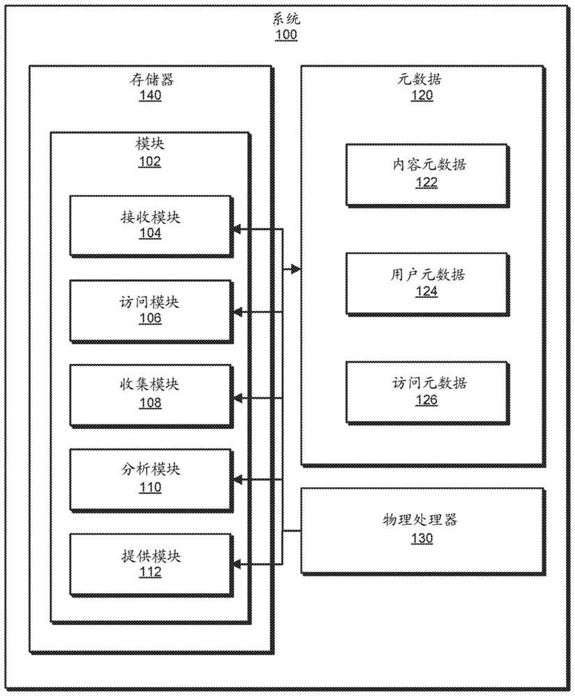
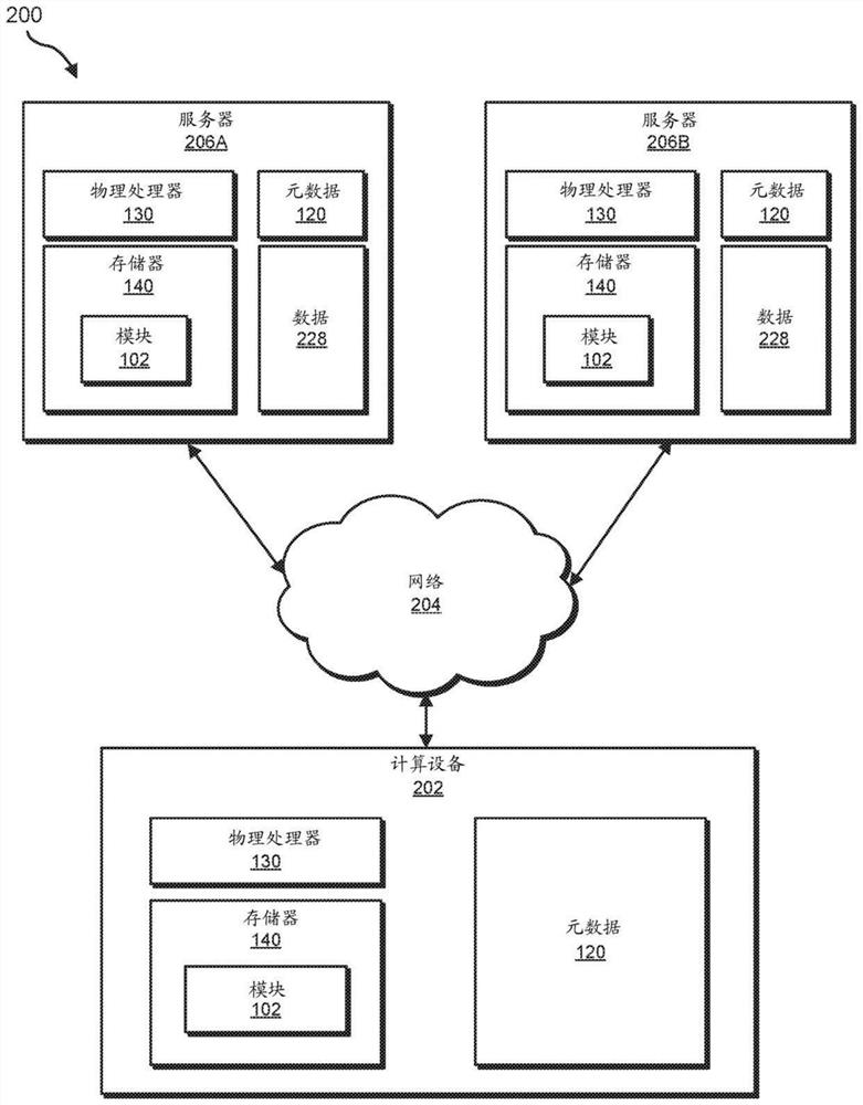
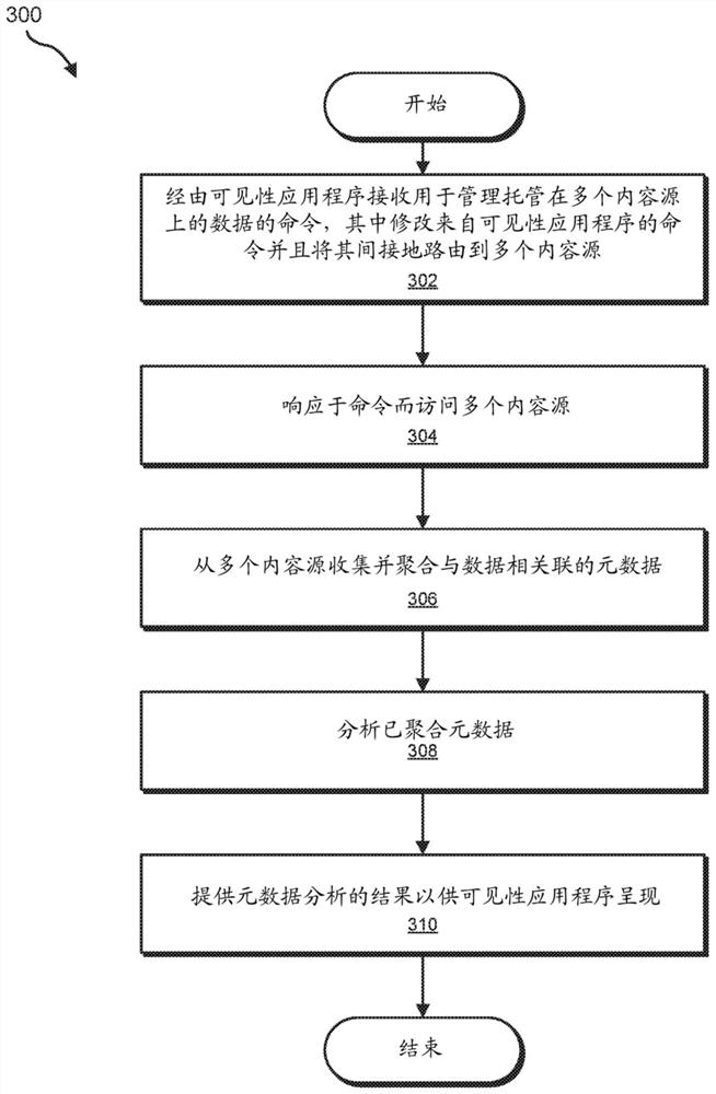
[0025] The present disclosure generally relates to systems and methods for data management of multiple cloud services. As organizations need to increase data storage requirements, they can rely on a variety of data storage solutions, including externally managed cloud-based services and/or internally managed local storage solutions. Without a predefined data model and/or due to various incompatibilities between storage solutions, the amount of unstructured data can grow to be too unmanageable. As will be explained in more detail below, a platform for multi-cloud data management can access multiple content sources storing data, and aggregate and analyze metadata associated with the data. The platform may provide an application programming interface (API) for a visibility application that can present analysis results and present a user interface for users to issue commands to the platform. The platform can provide tools through visibility applications to better manage unstructured data. For example, expired data can be deleted or archived to cheaper storage solutions. The systems and methods described herein can improve the use of computing resources and other resources required for data storage. This may allow businesses to better control data and better manage the costs and expenses associated with data storage.
[0026] In addition, the systems and methods described herein can improve the operation of computing devices by analyzing data to store data more efficiently and providing interfaces for effective data management. These systems and methods can also improve the field of data management by providing a platform that enables effective data storage.
[0027] Refer to below Figure 1 to Figure 2 Provides a detailed description of an exemplary system for data management of multiple cloud services. Will also combine image 3 Provide a detailed description of the corresponding computer-implemented method. Will combine Figure 4 Provides a detailed description of an exemplary platform architecture for data management of multiple cloud services. Will combine Figure 5 Provides a detailed description of an exemplary workflow for data management of multiple cloud services. In addition, combine separately Image 6 with Figure 7 A detailed description is provided of exemplary computing systems and network architectures capable of implementing one or more of the embodiments described herein.
[0028] figure 1 It is a block diagram of an exemplary system 100 for data management of multiple cloud services. As shown in this figure, the exemplary system 100 may include one or more modules 102 for performing one or more tasks. As will be explained in more detail below, the module 102 may include a receiving module 104, an access module 106, a collection module 108, an analysis module 110, and a providing module 112. Although shown as separate elements, figure 1 One or more of the modules 102 may represent a single module or parts of an application program.
[0029] In some embodiments, figure 1 One or more of the modules 102 in may represent one or more software applications or programs, which, when executed by a computing device, can cause the computing device to perform one or more tasks. For example, and as will be described in more detail below, one or more modules in module 102 may represent modules that are stored and configured to run on one or more computing devices, such as figure 2 (E.g., computing device 202 and/or servers 206A-B). figure 1 One or more of the modules 102 in may also represent all or part of one or more special purpose computers configured to perform one or more tasks.
[0030] Such as figure 1 As shown, the exemplary system 100 may also include one or more memory devices, such as memory 140. The memory 140 generally represents any type or form of volatile or non-volatile storage device or medium capable of storing data and/or computer readable instructions. In one example, the memory 140 may store, load, and/or maintain one or more modules in the module 102. Examples of the memory 140 include, but are not limited to, random access memory (RAM), read only memory (ROM), flash memory, hard disk drive (HDD), solid state drive (SSD), optical disk drive, high-speed cache, one or more of the foregoing Variations or combinations of and/or any other suitable memory.
[0031] Such as figure 1 As shown, the exemplary system 100 may also include one or more physical processors, such as physical processor 130. The physical processor 130 generally represents any type or form of hardware-implemented processing unit capable of interpreting and/or executing computer-readable instructions. In one example, the physical processor 130 may access and/or modify one or more modules of the modules 102 stored in the memory 140. Additionally or alternatively, the physical processor 130 may execute one or more of the modules 102 to facilitate data management of multiple cloud services. Examples of the physical processor 130 include, but are not limited to, a microprocessor, a microcontroller, a central processing unit (CPU), a field programmable gate array (FPGA) that implements a soft core processor, an application specific integrated circuit (ASIC), one or Parts of multiples, variations or combinations of one or more of the above, and/or any other suitable physical processors.
[0032] Such as figure 1 As shown, the exemplary system 100 may also include one or more additional elements, such as metadata 120. Metadata 120 usually represents and is hosted at the content source (e.g., figure 2 Data on servers 206A-B in figure 2 Data in 228) associated metadata of any type or form. The data can be, for example, files, documents, photos, videos, content, etc. Metadata 120 may represent information about data, such as various attributes and characteristics. In one example, the metadata 120 may include specific types of metadata, such as content metadata 122, user metadata 124, and access metadata 126. The content metadata 122 may represent metadata closely related to the data, such as file type, file size, file location, and so on. User metadata 124 may represent metadata associated with users who can access the data, such as user identification, user profile information (eg, department, manager, email address, etc.), permissions, group membership, and the like. The access metadata 126 may represent metadata of operation events associated with the data, including details of file operations on the data. Examples of accessing metadata 126 may include, but are not limited to, the timestamp, the user performing the operation, the type of operation (eg, file creation, modification, movement, etc.), and other related details.
[0033] figure 1 The exemplary system 100 in can be implemented in various ways. For example, all or part of the exemplary system 100 may represent figure 2 Part of an exemplary system 200 in. Such as figure 2 As shown, the system 200 may include a computing device 202 that communicates with servers 206A-B via a network 204. In one example, all or part of the functions of the module 102 may be performed by the computing device 202, the servers 206A-B, and/or any other suitable computing system. As will be described in more detail below, when executed by at least one processor of the computing device 202 and/or the server 206, figure 1 One or more of the modules 102 in may enable the computing device 202 and/or servers 206A-B to manage data from multiple cloud services. For example, and as will be described in more detail below, one or more of the modules 102 may cause the computing device 202 and/or the server 206A-B to enumerate and use figure 2 The method claims the steps.
[0034] Computing device 202 generally represents any type or form of computing device capable of reading computer-executable instructions. The computing device 202 may be a platform server, which may be a backend server hosting a platform for multi-cloud data management, as will be described below. Additional examples of computing device 202 include, but are not limited to, laptop computers, tablet computers, desktop computers, servers, cellular phones, personal digital assistants (PDAs), multimedia players, embedded systems, wearable devices (e.g., smart watches, Smart glasses, etc.), smart vehicles, smart packaging (for example, active or smart packaging), game consoles, so-called Internet of Things devices (for example, smart appliances, etc.), variations and combinations of one or more of the above, and/or any other Appropriate computing system.
[0035] Servers 206A-B generally represent any type or form of computing device capable of hosting content, such as data 228. The servers 206A-B may be cloud servers or servers hosting cloud services and/or other private data hosting services. Additional examples of the server 206 include, but are not limited to, back-end servers, application servers, web servers, storage servers, and/or those configured to run certain software applications and/or provide various web, storage, and/or database services The database server. Although in figure 2 Is shown as two entities in, but the servers 206A-B may include and/or represent multiple servers that work and/or operate in conjunction with each other.
[0036] Data 228 generally represents any type or form of data. Examples of data 228 may include, but are not limited to, files, documents, photos, videos, digital representations of information, and the like. Data 228 may be stored on and accessed from multiple servers (such as servers 206A-B). The data 228 may be unstructured data. As used herein, the term "unstructured data" generally refers to data that may not be organized in a predefined manner or otherwise do not have a predefined data model. Unstructured data (especially unstructured data hosted on various non-collaborative cloud services) can be difficult to manage because it scales in size and/or volume.
[0037] The network 204 generally represents any medium or architecture capable of facilitating communication or data transfer. In one example, the network 204 may facilitate communication between the computing device 202 and the server 206. In this example, the network 204 may use wireless and/or wired connections to facilitate communication or data transfer. Examples of the network 204 include, but are not limited to: intranet, wide area network (WAN), local area network (LAN), personal area network (PAN), internet, power line communication (PLC), cellular network (eg, Global System for Mobile communications (GSM) network ), parts of one or more of the above, variants or combinations of one or more of the above, and/or any other suitable network.
[0038] image 3 It is a flowchart of an exemplary computer-implemented method 300 for data management of multiple cloud services. image 3 The steps shown in can be executed by any suitable computer executable code and/or computing system, including figure 1 System in 100, figure 2 The system 200 in and/or a variation or combination of one or more of the above. In one example, image 3 Each step shown in may represent an algorithm whose structure includes and/or is represented by multiple sub-steps, examples of which will be provided in more detail below.
[0039] Such as image 3 As shown, at step 302, one or more of the systems described herein may receive a command for managing data hosted on multiple content sources via a visibility application, where the modification from the visibility application Command and route it indirectly to multiple content sources. For example, as figure 2 As part of the computing device 202, the receiving module 104 can receive commands for managing data 228.
[0040] As used herein, the term "visibility application" generally refers to an application that can be used to monitor application performance. Examples of visibility applications include, but are not limited to, diagnostic applications, security applications, management tools, etc. In some examples, a visibility application can more generally refer to an application that can be client-facing in order to provide a user interface and access the underlying platform and/or back-end services so that users may not directly access the platform.
[0041] Figure 4 A platform environment 400 including a visibility application 462, a presentation layer 460, a control plane 470, an analysis plane 480, a data plane 490, and content sources 406A-B is shown. The visibility application 462 may be a visibility application that interfaces with the presentation layer 460, but in some embodiments, the presentation layer 460 may include or otherwise integrate the visibility application 462. The platform 450 may be a multi-cloud data management platform that may include various microservices, and its architecture may be represented by a presentation layer 460, a control plane 470, an analysis plane 480, and a data plane 490. The multi-cloud data management platform may be implemented by the computing device 202, for example. The content sources 406A-B may correspond to various cloud services and may be implanted with the servers 206A-B.
[0042] The presentation layer 460 may provide an API for the visibility application 462 to interface with the platform 450. The presentation layer 460 may allow the development of various application programs that can interface with the platform 450. These applications can take advantage of the data management functions provided by the platform 450 without directly accessing cloud services (such as content sources 406A-B). The visibility application 462 may provide a user interface to the user to allow the user to issue commands and view the results.
[0043] The control plane 470 may provide control logic for coordinating actions between the various layers of the platform 450. For example, the control plane 470 may receive commands from the user via the visibility application 462 and the presentation layer 460. Therefore, the control plane 470 can modify the received commands and issue appropriate commands to the analysis plane 480 and/or the data plane 490 as needed to execute the received commands. The control plane 470 may also send the result of the executed command to the presentation layer 460 or facilitate sending the result of the executed command to the presentation layer.
[0044] The analysis plane 480 may provide analysis logic for performing analysis on the data stored in the content sources 406A-B. The analysis plane 480 may utilize one or more machine learning systems and/or other analysis tools to perform the analysis.
[0045] The data plane 490 may provide an interface for accessing content sources 406A-B. The data plane 490 may be configured to access various types of data storage solutions, such as cloud services, private data servers, database servers, and so on. The data plane 490 may facilitate communication between the platform 450 and content sources 406A-B.
[0046] In some embodiments, the platform 450 may be deployed on a single server or computing device. In other embodiments, the platform 450 may be deployed on multiple servers. For example, the data plane 490 may be deployed near the data 228, such as on a cloud service and/or private data server (eg, server 206A and/or server 206B). The analysis plane 480 may also be deployed near the data 228. In some embodiments, multiple iterations of the analysis plane 480 and/or the data plane 490 may be deployed, such as on each cloud service and/or private data server. The control plane 470 may be deployed in a centralized location close to the user, such as on a client computing device or a company server.
[0047] return image 3 The system described herein can perform step 302 in a variety of ways. In one example, the command may be a general command, such as a command to start analyzing data (eg, data 228) and/or continue the analysis. In one example, the command may be a broad command, such as a command to reorganize data. In one example, the command may be a specific command, such as a command to move and/or delete a specific file. In other examples, the command may not be a direct command from the user, but a command in response to the user initiating the visibility application 462 and the general platform 450.
[0048] In addition, the user may be authenticated first, so that the authenticated user issues the command. Go to Figure 5 , Figure 5 A workflow 500 using a multi-cloud data management platform, such as platform 450, is shown. At 502, the user may log into a visibility application, such as visibility application 462. At 504, the user can issue a command to the platform.
[0049] return image 3 At step 304, one or more of the systems described herein may access multiple content sources in response to commands. For example, as figure 2 As part of the computing device 202, the access module 106 can access the servers 206A-B.
[0050] The system described herein can perform step 304 in a variety of ways. In one example, the data plane 490 can access content sources 406A-B. The data plane 490 may be controlled by the control plane 470 to access content sources 406A-B in response to commands received from the visibility application 462 via the presentation layer 460.
[0051] Such as Figure 5 As shown, at 506, the control plane can issue a command to the data plane in response to the received command. The received command may be a command to initiate data analysis, and the command may include one or more sub-commands coordinated by the control plane 470. For example, data analysis may need to collect and aggregate data metadata, analyze metadata, and provide analysis results for presentation. In other examples, the received command may be a specific command for creating, modifying, moving, and/or deleting data, and the control plane 470 may modify the data accordingly to send appropriate commands to the data plane 490. For example, the control plane 470 may specify to the data plane 490 which of the content source 406A and/or content source 406B is to be accessed and which operations are to be performed.
[0052] return image 3 At step 306, one or more of the systems described herein may collect and aggregate metadata associated with the data from multiple content sources. For example, as figure 2 As part of the computing device 202 in the computing device 202, the collection module 108 may collect and aggregate metadata 120, which may include content metadata 122, user metadata 124, and/or access metadata 126 associated with data 228.
[0053] The system described herein can perform step 306 in a variety of ways. In one example, the metadata 120 may be stored with the data 228. In another example, the metadata 120 may be derived from the data 228, such as by examining and/or determining the characteristics of the data 228. Portions of metadata 120 (such as user metadata 124) may be stored separately from data 228, and may alternatively be obtained from another server (such as computing device 202) that stores user information.
[0054] As described above, the content metadata 122 may represent attributes and/or characteristics directly related to the data 228. The user metadata 124 may represent attributes and/or characteristics related to users who can access the data 228. The access metadata 126 may represent a history of actions and/or events related to the data 228. Compared to metadata from a single source, collecting and aggregating content metadata 122, user metadata 124, and access metadata 126 can provide a more complete set of metadata corresponding to data 228.
[0055] Such as Figure 5 As shown, at 508, the command issued by the data plane can be executed at the cloud service. For example, the data plane 490 may access the content source 406A and/or the content source 406B to collect available metadata (e.g., the content metadata 122 and/or the access metadata 126). The data plane 490 may also collect metadata (e.g., user metadata 124) from other sources, such as from the platform 450, as needed. In some examples, metadata 120 may include a subset of content metadata 122, user metadata 124, and/or access metadata 126. For example, one or more of content metadata 122, user metadata 124, and/or access metadata 126 may not be available.
[0056] At 510, the control plane may collect responses from 508. For example, the control plane 470 may use the data plane 490 to collect and aggregate metadata 120. In some examples, aggregating metadata 120 may include combining with previous aggregation of metadata 120.
[0057] return image 3 At step 308, one or more of the systems described herein may analyze the aggregated metadata. For example, as figure 2 As part of the computing device 202 in the computing device 202, the analysis module 110 may analyze the metadata 120, including content metadata 122, user metadata 124, and/or access metadata 126.
[0058] The system described herein can perform step 308 in a variety of ways. In one example, in Figure 5 At 512, the analysis plane can analyze the response collected at 510. For example, the control plane 470 may order the analysis plane 480 to analyze the metadata 120.
[0059] The results of the analysis can reveal various characteristics of the data 120. For example, the portions of the data 120 may be prioritized based on various factors. Accessible data can generally be given higher priority than data that cannot be accessed frequently or otherwise expired. Data accessed by higher-level members of the business (such as managers, administrators, team leaders, etc.) may be given higher priority than data not accessed by higher-level members. Data marked as important, confidential, protected, etc. can be given higher priority. Data integrity can also be considered. For example, corrupted or incomplete data can be given lower priority or marked for removal. It can further reveal other usage characteristics and heuristics.
[0060] return image 3 At step 310, one or more of the systems described herein may provide the results of metadata analysis for presentation by the visibility application program. For example, as figure 2 The providing module 112 can provide results for presentation as part of the computing device 202 in the.
[0061] The system described herein can perform step 310 in a variety of ways. In one example, in Figure 5 At 514, the presentation layer can present the result. For example, the presentation layer 460 may present results via the visibility application 462. The control plane 470 may instruct the presentation layer 460 to present the result. In some examples, the control plane 470 may also take actions to manage the data 228. For example, the control plane 470 can clean up expired data by deleting and/or archiving.
[0062] The control plane 470 may move portions of the data 228 to different storage devices of the content source 406A and/or content source 406B based on priority. The storage devices of the content sources 406A-B may be organized in a storage hierarchy that can prioritize the storage devices. The storage devices may be prioritized in the storage hierarchical structure based on the type, performance, cost, bandwidth, etc. of the storage devices, for example. For example, due to performance, flash-based storage devices may be higher in the hierarchy than disk-based storage devices, but can increase the cost of acquisition and/or maintenance.
[0063] In some examples, the user can send subsequent commands. For example, as figure 2 The receiving module 104 may receive a second command for managing data in response to the presentation of the result by the visibility application. The access module 106 can access multiple content services to execute the second command. Such as Figure 5 As shown, at 516, the user may respond to the presentation of results at 514. The user can issue another command to return to 504 and repeat part of the workflow 500 based on the command.
[0064] In some examples, the second command may include a command to move part of the data through the storage hierarchy based on metadata analysis. For example, high-priority data can move up the storage hierarchy, while low-priority data can move down the storage hierarchy.
[0065] In some examples, the second command may include a command to delete part of the data based on metadata analysis. For example, data that is not used, marked as unimportant, incomplete, damaged, or otherwise marked for deletion can be deleted in order to release storage resources.
[0066] As described above in connection with the exemplary method 300 and the workflow 500, a multi-cloud data management platform may allow multiple services, such as backup, copy data management, etc., to be built within the same technical framework. The platform can provide a single control point and a unified user experience for the workload, data and information management services of enterprise customers. The platform can take advantage of a comprehensive and unified view and status of the customer's infrastructure and information assets. The platform can also provide a business framework that can support the new business model to be built and supported. The platform may include a control plane, which includes a state machine with knowledge of various services in different life cycle stages (such as development, deployment, runtime, etc.). The platform may have separation of various planes (for example, data, control, analysis, etc.) with a distributed architecture. The platform can support multiple tenants and can allow customers to manage hybrid clouds. The platform can allow multiple applications to contribute and share a common asset model that can help derive and execute higher-level business strategies and goals.
[0067] Image 6 Is a block diagram of an exemplary computing system 610 capable of implementing one or more of the embodiments described and/or illustrated herein. For example, all or part of the computing system 610 may be executed alone or in combination with other elements and/or as a device for executing one or more of the steps described herein (such as image 3 One or more of the steps shown). All or part of the computing system 610 may also be executed and/or used as a device for executing any other steps, methods, or processes described and/or shown herein.
[0068] Computing system 610 refers in a broad sense to any single-processor or multi-processor computing device or system capable of executing computer-readable instructions. Examples of computing system 610 include, but are not limited to, workstations, laptop computers, client-side terminals, servers, distributed computing systems, handheld devices, or any other computing systems or devices. In its most basic configuration, the computing system 610 may include a system memory 616 and at least one processor 614.
[0069] The processor 614 generally represents any type or form of physical processing unit (for example, a central processing unit implemented by hardware) capable of processing data or interpreting and executing instructions. In some embodiments, the processor 614 may receive instructions from a software application or module. These instructions may cause the processor 614 to perform the functions of one or more exemplary implementations described and/or illustrated herein.
[0070] The system memory 616 generally represents any type or form of volatile or non-volatile storage device or medium capable of storing data and/or other computer-readable instructions. Examples of system memory 616 include, but are not limited to, random access memory (RAM), read only memory (ROM), flash memory, or any other suitable memory device. Although not required, in some embodiments, the computing system 610 may include both a volatile memory unit (such as the system memory 616) and a non-volatile storage device (such as the main storage device 632, as described in detail below). By. In one example, from figure 1 One or more of the modules 102 of the module may be loaded into the system memory 616.
[0071] In some examples, the system memory 616 may store and/or load the operating system 640 for execution by the processor 614. In one example, the operating system 640 may include and/or represent software that manages computer hardware and software resources and/or provides general services to computer programs and/or application programs on the computing system 610. Examples of operating system 640 include, but are not limited to, LINUX, JUNOS, MICROSOFT WINDOWS, WINDOWS MOBILE, MAC OS, APPLE'SIOS, UNIX, GOOGLE CHROME OS, GOOGLE'S ANDROID, SOLARIS, variants of one or more of the foregoing, and/or any Other suitable operating systems.
[0072] In some embodiments, in addition to the processor 614 and the system memory 616, the exemplary computing system 610 may also include one or more components or elements. For example, such as Image 6 As shown, the computing system 610 may include a memory controller 618, an input/output (I/O) controller 620, and a communication interface 622, each of which may be interconnected via a communication infrastructure 612. Communication infrastructure 612 generally represents any type or form of infrastructure capable of facilitating communication between one or more components of a computing device. Examples of communication infrastructure 612 include, but are not limited to, communication buses (such as Industry Standard Architecture (ISA), Peripheral Component Interconnect (PCI), PCI Express (PCIe), or similar buses) and networks.
[0073] The memory controller 618 generally represents any type or form of device capable of processing memory or data or controlling communication between one or more components of the computing system 610. For example, in some embodiments, the memory controller 618 may control the communication between the processor 614, the system memory 616, and the I/O controller 620 via the communication infrastructure 612.
[0074] The I/O controller 620 generally represents any type or form of module capable of coordinating and/or controlling the input function and output function of the computing device. For example, in certain embodiments, the I/O controller 620 can control or facilitate data transfer between one or more elements of the computing system 610, such as the processor 614, system memory 616, communication interface 622, Display adapter 626, input interface 630, and storage interface 634.
[0075] Such as Image 6 As shown, the computing system 610 may also include at least one display device 624 that is coupled to the I/O controller 620 via the display adapter 626. The display device 624 generally represents any type or form of device that can visually display the information forwarded by the display adapter 626. Similarly, the display adapter 626 generally represents any type or form configured to forward graphics, text, and other data from the communication infrastructure 612 (or from the frame buffer, as known in the art) for display on the display device 624 device of.
[0076] Such as Image 6 As shown, the exemplary computing system 610 may also include at least one input device 628 that is coupled to the I/O controller 620 via the input interface 630. Input device 628 generally represents any type or form of input device capable of providing computer or human-generated input to the exemplary computing system 610. Examples of input device 628 include, but are not limited to, keyboards, pointing devices, voice recognition devices, variations or combinations of one or more of the foregoing, and/or any other input devices.
[0077] Additionally or alternatively, the exemplary computing system 610 may include additional I/O devices. For example, the exemplary computing system 610 may include an I/O device 636. In this example, the I/O device 636 may include and/or represent a user interface that facilitates human-computer interaction with the computing system 610. Examples of I/O devices 636 include, but are not limited to, computer mice, keyboards, monitors, printers, modems, cameras, scanners, microphones, touch screen devices, variations or combinations of one or more of the foregoing, and/or any other I /O equipment.
[0078] The communication interface 622 broadly represents any type or form of communication device or adapter capable of facilitating communication between the exemplary computing system 610 and one or more additional devices. For example, in some embodiments, the communication interface 622 can facilitate communication between the computing system 610 and a private or public network that includes additional computing systems. Examples of the communication interface 622 include, but are not limited to, a wired network interface (such as a network interface card), a wireless network interface (such as a wireless network interface card), a modem, and any other suitable interface. In at least one embodiment, the communication interface 622 may provide a direct connection to a remote server via a direct link to a network, such as the Internet. The communication interface 622 may also provide such a connection indirectly through, for example, a local area network (such as an Ethernet network), a personal area network, a telephone or cable network, a cellular phone connection, a satellite data connection, or any other suitable connection.
[0079] In certain embodiments, the communication interface 622 may also represent a host adapter configured to facilitate communication between the computing system 610 and one or more additional networks or storage devices via an external bus or communication channel. Examples of host adapters include, but are not limited to, Small Computer System Interface (SCSI) host adapters, Universal Serial Bus (USB) host adapters, Institute of Electrical and Electronics Engineers (IEEE) 1394 host adapters, Advanced Technology Attachment (ATA), Parallel ATA ( PATA), Serial ATA (SATA) and external SATA (eSATA) host adapters, Fibre Channel interface adapters, Ethernet adapters, etc. The communication interface 622 may also allow the computing system 610 to participate in distributed or remote computing. For example, the communication interface 622 may receive instructions from a remote device or send instructions to the remote device for execution.
[0080] In some examples, the system memory 616 may store and/or load the network communication program 638 for execution by the processor 614. In one example, the network communication program 638 may include and/or represent enabling the computing system 610 to communicate with another computing system ( Image 6 Not shown in) software that establishes a network connection 642 and/or communicates with another computing system through a communication interface 622. In this example, the network communication program 638 may direct the flow of outgoing traffic sent to another computing system via the network connection 642. Additionally or alternatively, the network communication program 638 may be combined with the processor 614 to direct the processing of incoming traffic received from other computing systems via the network connection 642.
[0081] Although not in Image 6 Is shown in this way in, but the network communication program 638 may alternatively be stored and/or loaded in the communication interface 622. For example, the network communication program 638 may include and/or represent at least a part of software and/or firmware executed by a processor and/or an application specific integrated circuit (ASIC) incorporated in the communication interface 622.
[0082] Such as Image 6 As shown, the exemplary computing system 610 may also include a main storage device 632 and a backup storage device 633 coupled to the communication infrastructure 612 via a storage interface 634. Storage devices 632 and 633 generally represent any type or form of storage devices or media capable of storing data and/or other computer-readable instructions. For example, the storage devices 632 and 633 may be magnetic disk drives (for example, so-called hard disk drives), solid state drives, floppy disk drives, tape drives, optical disk drives, flash drives, and the like. The storage interface 634 generally represents any type or form of interface or device used to transfer data between the storage devices 632 and 633 and other components of the computing system 610. In one example, from figure 1 The metadata 120 may be stored and/or loaded in the main storage device 632.
[0083] In some embodiments, the storage devices 632 and 633 may be configured to perform reading and/or writing to a removable storage unit configured to store computer software, data, or other computer-readable information. Examples of suitable removable storage units include, but are not limited to, floppy disks, magnetic tapes, optical disks, flash memory devices, and the like. The storage device 632 and the storage device 633 may also include other similar structures or devices for allowing computer software, data or other computer readable instructions to be loaded into the computing system 610. For example, the storage device 632 and the storage device 633 may be configured to read and write software, data, or other computer-readable information. The storage devices 632 and 633 may also be part of the computing system 610, or may be independent devices accessed through other interface systems.
[0084] Many other devices or subsystems can be connected to the computing system 610. On the contrary, Image 6 The presence of the components and devices shown are not necessarily all in order to practice the embodiments described and/or shown herein. The equipment and subsystems mentioned above can also be Image 6 The different ways shown are interconnected. The computing system 610 may also adopt any number of software configurations, firmware configurations, and/or hardware configurations. For example, one or more of the exemplary embodiments disclosed herein may be encoded as a computer program on a computer-readable medium (also referred to as computer software, software application, computer-readable instructions, or computer control logic). ). As used herein, the term "computer-readable medium" generally refers to any form of device, carrier, or medium that can store or carry computer-readable instructions. Examples of computer-readable media include, but are not limited to, transmission-type media, such as carrier waves, and non-transitory-type media, such as magnetic storage media (e.g., hard drives, tape drives, and floppy disks), optical storage media (e.g., compact disks (CDs)) , Digital Video Disk (DVD), BLU-RAY Disk), electronic storage media (for example, solid-state drives and flash memory media) and other distribution systems.
[0085] A computer-readable medium containing a computer program can be loaded into the computing system 610. Then all or part of the computer program stored on the computer readable medium may be stored in the system memory 616 and/or in various parts of the storage devices 632 and 633. When executed by the processor 614, the computer program loaded into the computing system 610 can cause the processor 614 to perform the functions of one or more of the embodiments described and/or shown herein and/or can cause processing The device becomes a device for performing the functions of one or more of the exemplary embodiments described and/or illustrated herein. Additionally or alternatively, one or more of the exemplary embodiments described and/or illustrated herein may be implemented in firmware and/or hardware. For example, the computing system 610 may be configured as an application specific integrated circuit (ASIC) suitable for implementing one or more of the exemplary embodiments disclosed herein.
[0086] Figure 7 It is a block diagram of an exemplary network architecture 700 in which client systems 710, 720, and 730 and servers 740 and 745 can be coupled to the network 750. As described in detail above, all or part of the network architecture 700 can be executed alone or in combination with other elements and/or as a device for executing one or more of the steps disclosed herein (such as image 3 One or more of the steps shown). All or part of the network architecture 700 may also be used to perform and/or as a device for performing other steps and features set forth in this disclosure.
[0087] The client systems 710, 720, and 730 generally represent any type or form of computing devices or systems, such as Image 6 Exemplary computing system 610 in. Similarly, servers 740 and 745 generally represent computing devices or systems configured to provide various database services and/or run certain software applications, such as application servers or database servers. Network 750 generally represents any telecommunications or computer network, including, for example, an intranet, WAN, LAN, PAN, or the Internet. In one example, the client systems 710, 720, and/or 730 and/or the server 740 and/or 745 may include figure 1 All or part of the system 100.
[0088] Such as Figure 7 As shown, one or more storage devices 760(1)-(N) may be directly attached to the server 740. Similarly, one or more storage devices 770(1)-(N) can be directly attached to the server 745. Storage devices 760(1)-(N) and storage devices 770(1)-(N) generally represent any type or form of storage devices or media capable of storing data and/or other computer-readable instructions. In some embodiments, storage devices 760(1)-(N) and storage devices 770(1)-(N) may represent network attached storage (NAS) configured to communicate with servers 740 and 745 using various protocols. ) Device, the protocol such as Network File System (NFS), Server Message Block (SMB) or Common Internet File System (CIFS).
[0089] The servers 740 and 745 may also be connected to a storage area network (SAN) structure 780. The SAN fabric 780 generally represents any type or form of computer network or architecture capable of facilitating communication between multiple storage devices. The SAN fabric 780 can facilitate communication between the servers 740 and 745 and the multiple storage devices 790(1)-(N) and/or the intelligent storage array 795. The SAN structure 780 can also facilitate the communication between the client systems 710, 720, and 730 and the storage devices 790(1)-(N) and/or the intelligent storage array 795 via the network 750 and the servers 740 and 745. In order for devices 790(1)-(N) and array 795 to appear as locally attached devices for client systems 710, 720, and 730. Like storage devices 760(1)-(N) and storage devices 770(1)-(N), storage devices 790(1)-(N) and smart storage arrays 795 generally represent the ability to store data and/or other computer Any type or form of storage device or medium that reads instructions.
[0090] In certain embodiments, and with reference to Image 6 An exemplary computing system 610, a communication interface (such as Image 6 The communication interface 622) can be used to provide connectivity between each of the client systems 710, 720, and 730 and the network 750. The client systems 710, 720, and 730 may be able to access information on the server 740 or 745 using, for example, a web browser or other client software. Such software can allow client systems 710, 720, and 730 to access the server 740, server 745, storage device 760(1)-(N), storage device 770(1)-(N), storage device 790(1)- (N) or data hosted by the smart storage array 795. although Figure 7 The use of a network (such as the Internet) to exchange data is depicted, but the embodiments described and/or illustrated herein are not limited to the Internet or any particular network-based environment.
[0091] In at least one embodiment, all or a part of one or more exemplary embodiments disclosed herein may be coded as a computer program and loaded into the server 740, the server 745, the storage device 760(1)-(N), The storage device 770(1)-(N), the storage device 790(1)-(N), the smart storage array 795, or any combination of them are executed. All or part of one or more exemplary embodiments disclosed herein may also be encoded as a computer program, stored in the server 740, run by the server 745, and distributed to the client systems 710, 720, and 730 through the network 750 .
[0092] As detailed above, one or more components of the computing system 610 and/or the network architecture 700 may be executed alone or in combination with other elements and/or used as a device for performing data management for multiple cloud services One or more steps of the exemplary method.
[0093] Although the foregoing disclosure uses specific block diagrams, flowcharts, and examples to illustrate various embodiments, each block diagram component, flowchart step, operation, and/or component described and/or illustrated herein may use a variety of hardware, software, or firmware (Or any combination of them) the configuration is implemented separately and/or collectively. In addition, any disclosure of components contained within other components should be regarded as exemplary in nature, as many other architectures can be implemented to achieve the same function.
[0094] In some examples, figure 1 All or part of the exemplary system 100 in may represent part of a cloud computing or network-based environment. The cloud computing environment can provide various services and applications via the Internet. These cloud-based services (for example, software as a service, platform as a service, infrastructure as a service, etc.) can be accessed through a web browser or other remote interface. The various functions described herein can be provided through a remote desktop environment or any other cloud-based computing environment.
[0095] In various embodiments, figure 1 All or part of the exemplary system 100 in may facilitate multiple tenancy within a cloud-based computing environment. In other words, the software modules described herein can configure a computing system (eg, a server) to facilitate multi-tenant applications for one or more of the functions described herein. For example, one or more of the software modules described herein can program the server to allow two or more clients (eg, customers) to share an application program running on the server. A server programmed in this way can share applications, operating systems, processing systems, and/or storage systems among multiple customers (ie, tenants). One or more of the modules described herein may also partition the data and/or configuration information of the multi-tenant application for each customer so that one customer cannot access the data and/or configuration information of another customer.
[0096] According to various implementations, figure 1 All or part of the exemplary system 100 in may be implemented within a virtual environment. For example, the modules and/or data described herein may reside and/or execute in a virtual machine. As used herein, the term "virtual machine" generally refers to any operating system environment extracted from computing hardware by a virtual machine manager (for example, a hypervisor). Additionally or alternatively, the modules and/or data described herein may reside and/or execute within the virtualization layer. As used herein, the term "virtualization layer" generally refers to any data layer and/or application layer that covers the operating system environment and/or is extracted from the operating system environment. The virtualization layer may be managed by a software virtualization solution (e.g., file system filter) that presents the virtualization layer as if it were part of the underlying basic operating system. For example, a software virtualization solution may redirect calls originally directed to locations in the basic file system and/or registry to locations in the virtualization layer.
[0097] In some examples, figure 1 All or part of the exemplary system 100 in may represent part of a mobile computing environment. The mobile computing environment can be implemented by a variety of mobile computing devices, including mobile phones, tablets, e-book readers, personal digital assistants, wearable computing devices (for example, computing devices with head-mounted displays, smart Watches etc.), etc. In some examples, the mobile computing environment may have one or more distinctive features, including, for example, reliance on battery power, only one foreground application present at any given time, remote management features, touch screen features, (e.g., by the Global Positioning System, Location and movement data provided by gyroscopes, accelerometers, etc., restricted platforms used to limit the modification of system-level configurations and/or limit the ability of third-party software to check the behavior of other applications, and to restrict the installation of applications (For example, only to install controls from approved application stores), and so on. The various functions described herein can be provided for and/or can interact with a mobile computing environment.
[0098] The computing devices and systems described and/or shown herein broadly refer to any type or form of computing devices or systems capable of executing computer-readable instructions, such as those contained within the modules described herein. In their most basic configuration, these computing devices may each include at least one memory device and at least one physical processor.
[0099] In some examples, the term "memory device" generally refers to any type or form of volatile or non-volatile storage device or medium capable of storing data and/or computer readable instructions. In one example, the memory device can store, load, and/or maintain one or more of the modules described herein. Examples of memory devices include, but are not limited to, random access memory (RAM), read only memory (ROM), flash memory, hard disk drive (HDD), solid state drive (SSD), optical drive, high-speed cache, one or more of the foregoing Variations or combinations of, or any other suitable memory.
[0100] In some examples, the term "physical processor" generally refers to any type or form of hardware-implemented processing unit capable of interpreting and/or executing computer-readable instructions. In one example, the physical processor can access and/or modify one or more modules stored in the aforementioned memory device. Examples of physical processors include, but are not limited to, microprocessors, microcontrollers, central processing units (CPUs), field programmable gate arrays (FPGAs) that implement soft-core processors, application-specific integrated circuits (ASICs), one of the above, or Parts of multiples, variations or combinations of one or more of the foregoing, or any other suitable physical processor.
[0101] The process parameters and sequence of steps described and/or shown herein are only given by way of example and can be changed as needed. For example, although the steps shown and/or described herein may be shown or discussed in a specific order, these steps need not be performed in the order shown or discussed. The various example methods described and/or illustrated herein may also omit one or more of the steps described or illustrated herein, or include additional steps in addition to those steps disclosed.
[0102] Although various embodiments have been described and/or shown herein in the context of a full-featured computing system, one or more of these exemplary embodiments may be distributed as various forms of program products, regardless of the use of The specific type of computer-readable medium that is actually distributed. The embodiments disclosed herein can also be implemented using software modules that perform certain tasks. These software modules may include script files, batch files, or other executable files that may be stored on a computer-readable storage medium or in a computing system. In some embodiments, these software modules can configure the computing system to perform one or more of the exemplary embodiments disclosed herein.
[0103] Although shown as separate elements, the modules described and/or shown herein may represent a single module or portions of an application. In addition, in some embodiments, one or more of these modules may represent one or more software applications or programs, which when executed by a computing device can cause the computing device to perform one or more tasks. For example, one or more of the modules described and/or illustrated herein may represent a module that is stored and configured to run on one or more of the computing devices or systems described and/or illustrated herein . One or more of these modules may also represent all or part of one or more special purpose computers configured to perform one or more tasks.
[0104] In addition, one or more of the modules described herein can transform data, physical devices, and/or representations of physical devices from one form to another. For example, one or more of the modules listed in this article can receive metadata to be converted, convert metadata, output conversion results to present analysis, use conversion results to manage associated data, and store conversion results to execute data Management function. In addition or alternatively, one or more of the modules described herein can be executed on a computing device, storing data on the computing device, and/or interacting with the computing device in other ways to connect the processor , Volatile memory, non-volatile memory, and/or any other part of a physical computing device converted from one form to another.
[0105] In some embodiments, the term "computer-readable medium" generally refers to any form of device, carrier, or medium that can store or carry computer-readable instructions. Examples of computer-readable media include, but are not limited to, transmission-type media, such as carrier waves, and non-transitory-type media, such as magnetic storage media (for example, hard disk drives, tape drives, and floppy disks), optical storage media (for example, compact disks (CD) , Digital Video Disk (DVD), BLU-RAY Disk), electronic storage media (for example, solid-state drives and flash memory media) and other distribution systems.
[0106] Although the foregoing disclosure uses specific block diagrams, flowcharts, and examples to illustrate various embodiments, each block diagram component, flowchart step, operation, and/or component described and/or illustrated herein may use a variety of hardware, software, or firmware (Or any combination of them) the configuration is implemented separately and/or collectively. In addition, any disclosure of components contained within other components should be regarded as exemplary in nature, as many other architectures can be implemented to achieve the same function.
[0107] The process parameters and sequence of steps described and/or shown herein are given by way of example only and can be changed as needed. For example, although the steps shown and/or described herein may be shown or discussed in a specific order, these steps need not be performed in the order shown or discussed. The various example methods described and/or illustrated herein may also omit one or more of the steps described or illustrated herein, or include additional steps in addition to those steps disclosed.
[0108] Although various embodiments have been described and/or shown herein in the context of a full-featured computing system, one or more of these exemplary embodiments may be distributed as various forms of program products, regardless of the use of The specific type of computer-readable medium that is actually distributed. The embodiments disclosed herein can also be implemented using modules that perform certain tasks. These modules can include script files, batch files, or other executable files that can be stored on a computer-readable storage medium or in a computing system. In some embodiments, these modules can configure the computing system to perform one or more of the exemplary embodiments disclosed herein.
[0109] The foregoing description is intended to enable others skilled in the art to make best use of the various aspects of the exemplary embodiments disclosed herein. This exemplary description is not intended to be exhaustive or limited to any exact form disclosed. Many modifications and changes can be made without departing from the spirit and scope of the present disclosure. The embodiments disclosed herein should be regarded as illustrative in all aspects and not restrictive. The scope of the present disclosure should be determined with reference to the appended claims and their equivalents.
[0110] Unless otherwise specified, the terms "connected to" and "coupled to" (and their derivatives) used in this specification and claims should be understood as allowing both direct connection and indirect (ie, via other elements). Or parts) connection. In addition, the terms "a" or "an" used in this specification and claims should be understood to mean "at least one...". Finally, for ease of use, the terms "including" and "having" (and their derivative forms) used in the specification and claims are interchangeable with the word "comprising" and have the same meaning as the word "comprising".

PUM

no PUM

Description & Claims & Application Information

We can also present the details of the Description, Claims and Application information to help users get a comprehensive understanding of the technical details of the patent, such as background art, summary of invention, brief description of drawings, description of embodiments, and other original content. On the other hand, users can also determine the specific scope of protection of the technology through the list of claims; as well as understand the changes in the life cycle of the technology with the presentation of the patent timeline. Login to view more.
Why Eureka
Try Eureka