Aerial fog generating device
A technology for generating device and aerosol, applied in the direction of tobacco, etc., can solve problems such as difficulty in structure setting
- Summary
- Abstract
- Description
- Claims
- Application Information
AI Technical Summary
Problems solved by technology
Method used
Image
Examples
Embodiment 1
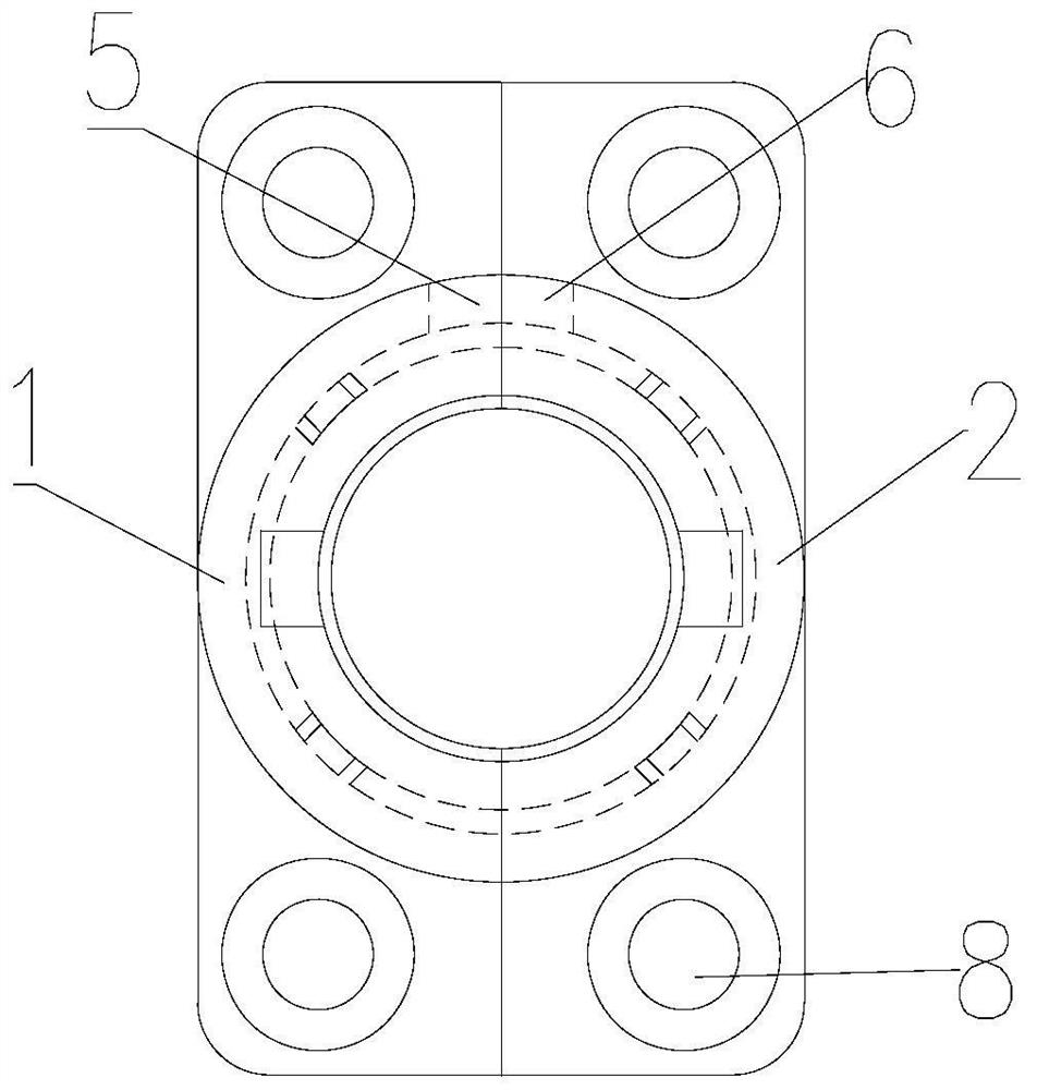
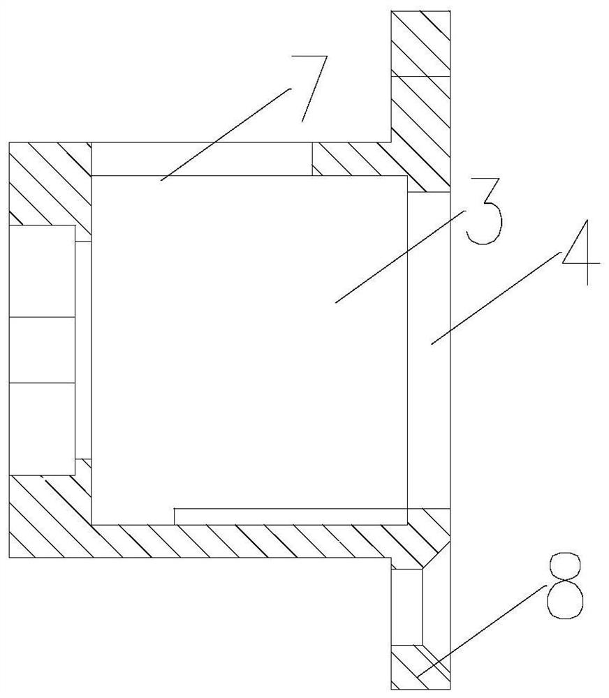
[0040] like Figure 1-5 As shown, in the present embodiment, the receiving cavity 3 is a cylindrical structure, and the heater is installed at one end of the receiving cavity 3, and the pushing structure includes: a strip hole 7, which is arranged on the side wall of the receiving cavity 3, and the strip hole 7 is arranged along the receiving cavity 3. The cavity 3 extends axially; the push rod 10 extends radially along the receiving cavity 3, the push rod 10 passes through the strip hole 7, one end thereof is connected with the receiving cavity 9, and the other end is freely arranged and arranged outside the receiving cavity 3, so that The user can push the free end of the push rod 10 along the extending direction of the strip hole 7 to push the accommodating chamber 9 to make the heater contact and separate from the aerosol forming substrate.
[0041] The present invention realizes the pushing of the accommodating cavity 9 through the above arrangement, and meanwhile, the st...
Embodiment 2
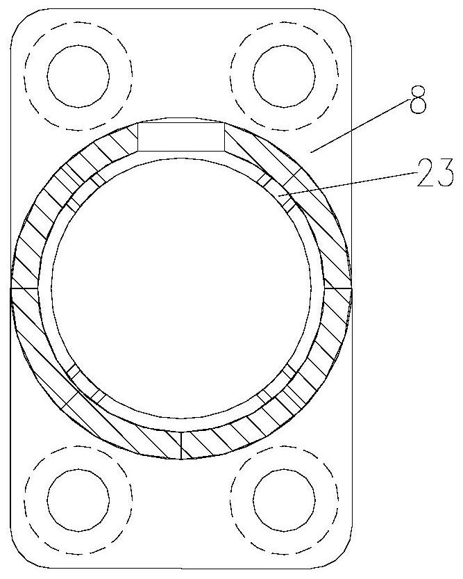
[0044] like Figure 1-5 As shown, the difference between this embodiment and the above-mentioned first embodiment is that the side wall of the receiving chamber 3 is provided with an inwardly protruding slide groove 23 extending axially along the receiving chamber 3, and the accommodating chamber 9 is provided with an outwardly protruding The protrusion 11 is placed in the sliding groove 23 and can slide in the sliding groove 23; the sliding groove 23 includes a plurality of extending around the axis of the receiving cavity 3, and the protrusion 11 includes a one-to-one corresponding Multiple.
[0045] The present invention improves the stability of the accommodating cavity 9 pushing through the above arrangement.
[0046] Specifically, the opposite side walls of the protrusion 11 are in conflict with the opposite side walls of the chute 23, the end of the protrusion 11 is in conflict with the bottom wall of the chute 23, and the outer circumference of the opening of the chut...
Embodiment 3
[0048] like Figure 1-3 As shown, the difference between this embodiment and the first and second embodiments above is that the first cavity 1 and the second cavity 2 are concave structures extending along the movement direction of the accommodating cavity 9 respectively, and the opening of the first cavity 1 and the second cavity The openings of the cavities 2 are oppositely arranged, and the edge of the opening of the first cavity 1 is connected with the edge of the opening of the second cavity 2 to form a receiving cavity 3 .
[0049] The present invention further reduces the difficulty of setting the structure of the receiving chamber 3 through the above arrangement.
[0050] Specifically, the radial sections of the inner and outer walls of the first cavity 1 and the radial sections of the inner and outer walls of the second cavity 2 are respectively semicircular, and the radial section of the receiving cavity 3 is circular. The receiving cavity 9 is a cylindrical structur...
PUM
 Abstract
Description
Claims
Application Information
 - R&D
- Intellectual Property
- Life Sciences
- Materials
- Tech Scout
- Unparalleled Data Quality
- Higher Quality Content
- 60% Fewer Hallucinations
Browse by: Latest US Patents, China's latest patents, Technical Efficacy Thesaurus, Application Domain, Technology Topic, Popular Technical Reports.
© 2025 PatSnap. All rights reserved.Legal|Privacy policy|Modern Slavery Act Transparency Statement|Sitemap|About US| Contact US: help@patsnap.com


