Cantilever-type tower crane foundation structure and construction method thereof

A technology of tower crane foundation and cantilever type, which is applied in the direction of foundation structure engineering and construction, which can solve the problems of unsatisfactory surroundings and limited plane position of tower crane foundation, and achieve the effects of reducing the structure size, reducing the difficulty of setting, and protecting corrosion

Pending Publication Date: 2019-12-13
CCCC SHEC SECOND ENG
View PDF0 Cites 2 Cited by
  • Summary
  • Abstract
  • Description
  • Claims
  • Application Information

AI Technical Summary

Problems solved by technology

[0007] The purpose of the present invention is to provide a cantilever tower crane foundation structure and its construction method. The first purpose is to solve the problem that the plane position of the tower crane foundation is limited and the surrounding area does not satisfy the independent foundation setting; the second purpose is to reduce the difficulty of tower crane foundation setting

Method used


Image

  • Cantilever-type tower crane foundation structure and construction method thereof
  • Cantilever-type tower crane foundation structure and construction method thereof
  • Cantilever-type tower crane foundation structure and construction method thereof

Examples


Embodiment approach 1

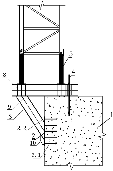
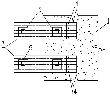
[0035] The cantilever type tower crane basic structure provided by the invention, such as figure 1 , figure 2 As shown, it at least includes a cap 1, a shaped steel corbel 3 and a tower crane embedded foundation 5, and the side of the cap 1 is provided with a plurality of pre-embedded steel plates 2, and the profiled steel corbel 3 is provided with two groups, and each group of shaped steel The corbels 3 independently carry the two feet of the pre-embedded foundation 5 of the tower crane. One end of each set of shaped steel corbels 3 is fixed on the platform 1, and the other end of the shaped steel corbels 3 is suspended in the air. The shaped steel corbels 3 are fixed on One end of the bearing platform 1 is counter-pressed by prestressed steel bar 4;

[0036] In the present invention, steel is used as the cantilever corbel structure, and the installation position of the tower crane is extended from the range of reinforced concrete to outside the range of reinforced concrete...

Embodiment approach 2

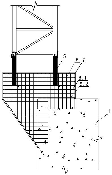
[0038] Embodiment 2 of the present invention relates to a cantilever type tower crane foundation structure, such as figure 1 As shown, it includes a cap 1, a section steel corbel 3 and a tower crane embedded foundation 5, the side of the cap 1 is provided with a plurality of pre-embedded steel plates 2, and the section steel corbel 3 is provided with two groups, each group of section steel The corbel 3 independently carries the two foundation feet of the embedded foundation 5 of the tower crane. Further, the profiled steel corbel 3 is composed of horizontal braces and diagonal braces, and is welded as a whole with the embedded steel plate 2. Preferably, the One end of the horizontal brace is fixed on the bearing platform 1, and the prestressed steel bar 4 is used for back pressure; the other end of the horizontal brace is suspended, and a plurality of vertical stiffening plates-8 are arranged inside the horizontal brace; One end of the brace is connected to the suspended end o...

Embodiment approach 3

[0042] Embodiment 3 of the present invention relates to a cantilevered tower crane foundation structure, which includes a cap 1, a steel corbel 3 and a pre-embedded tower crane foundation 5, the side of the cap 1 is provided with a plurality of pre-embedded steel plates 2, the There are two groups of shaped steel corbels 3, each group of shaped steel corbels 3 independently bears two feet of the pre-buried foundation 5 of the tower crane, one end of each set of shaped steel corbels 3 is fixed on the bearing platform 1, and the other end of the shaped steel corbels 3 One end is suspended in the air, and the suspended end of the shaped steel corbel 3 is connected to the embedded steel plate 2; the other end of the shaped steel corbel 3 fixed on the platform 1 is back-pressed by prestressed steel bar 4, such as figure 2As shown, further, each group of shaped steel corbels 3 is fixed on the bearing platform 1 through at least four prestressed steel bars 4, the prestressed steel ba...


PUM


Abstract

The invention provides a cantilever-type tower crane foundation structure and a construction method thereof. Shape steel is utilized as cantilever bracket structures, the mounting position of a towercrane extends out of the reinforced concrete range from the interior of the reinforced concrete range for balancing the bending moment and shearing force which are transmitted to a foundation from thetower crane, and the problems that the plane position of the tower crane foundation is limited, and the periphery does not meet independent foundation arrangement are solved; prestressed steel bars are utilized as main force-bearing components of an anchoring structure, and shape steel brackets and a bearing platform are in frictional connection by applying pretension force; a reinforced concretestructure is adopted as a protection structure to lower the influence caused by a collision of external force to the shape steel brackets and protect against corrosion caused by the environmental influence; and through the structure, the arrangement difficulty of the tower crane is lowered, the construction size of the tower crane foundation is decreased to the greatest extent under the limited working condition, the distances between the tower crane and attachments are reduced, a tower crane wall-adhering structure is simplified, and practicability is high.

Description

technical field [0001] The invention relates to the field of tower crane installation and construction, in particular to a cantilever type tower crane foundation structure and a construction method suitable for water and restricted areas. Background technique [0002] Tower crane is the most commonly used lifting equipment on construction sites, also known as "tower crane", which is used to lift construction materials such as steel bars, corrugated wood, concrete, and steel pipes. Tower crane is an indispensable equipment on the construction site. [0003] In order to ensure the stability and safety of the tower crane, the tower crane is installed on the foundation of the tower crane. The foundation of the tower crane is usually composed of a large-sized concrete cap. Most of the existing tower crane foundations are made on site, and the production period is long. It is reused and needs to be removed after use, and the studs are difficult to remove, which is prone to safety...

Claims


Application Information

Patent Timeline
Patent Type & Authority Applications(China)
IPC IPC(8): E02D27/42
CPCE02D27/42
Inventor 梁磊磊徐财进王培刘英健韩伦孔聪
Owner CCCC SHEC SECOND ENG
Why Eureka
Try Eureka