
Sensor system, including a plurality of individual and separate sensor elements

A sensor device and sensor element technology, which is applied in the direction of transmitting sensing components, measuring devices, and microstructure devices using electric/magnetic devices, can solve the problems of high development cost, difficulty in using size-sensitive applications, and high overhead. The effect of reducing overhead

Pending Publication Date: 2021-10-22
ROBERT BOSCH GMBH
View PDF3 Cites 0 Cited by
  • Summary
  • Abstract
  • Description
  • Claims
  • Application Information

AI Technical Summary

Problems solved by technology

However, depending on the complexity of the improvements, high development costs are required, especially if disruptive rather than just incremental performance improvements are required
[0004] For example, low-noise signals can be obtained by evaluating the signals of several sensor elements, as can be seen, for example, from US 2006 0 082 463 A1; however, the disadvantage here is that the overall system integration requires a relatively high outlay, and size prohibits use in size sensitive applications or at least makes it very difficult

Method used


Image

  • Sensor system, including a plurality of individual and separate sensor elements
  • Sensor system, including a plurality of individual and separate sensor elements
  • Sensor system, including a plurality of individual and separate sensor elements

Examples


Embodiment Construction

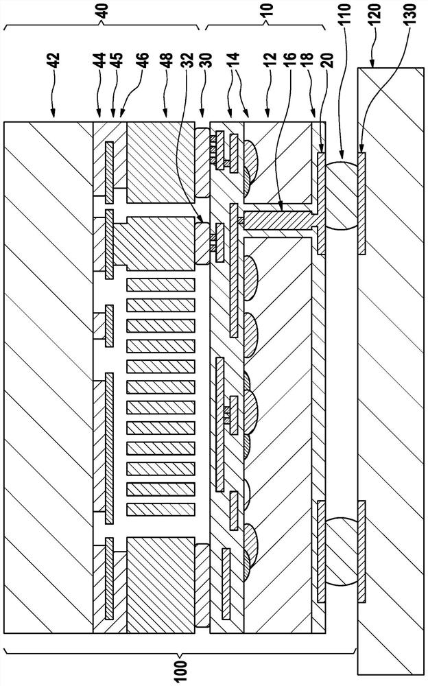
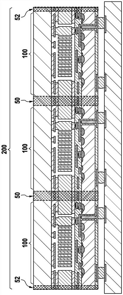
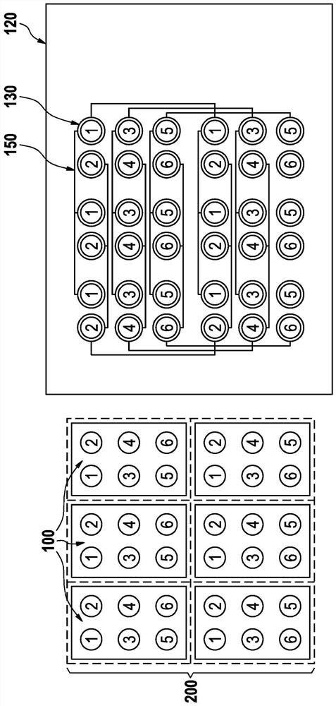
[0021] As an example implementation, in figure 1 A sensor device 200 according to the invention is shown in a schematic side view (cf. figure 2 ) A cross-sectional view of a single and separated sensor element 100. therefore, figure 1The basic configuration of an individual sensor element according to the invention is shown, wherein the sensor device 200 has a plurality of such sensor elements 100 or individual sensor elements 100 , in particular a plurality of such sensor elements 100 of the same type or identical design. . In particular, the individual sensor element 100 is realized as a so-called ASICap-MEMS component 100 , ie it has a first substrate 42 with a micromechanical sensor structure and a second substrate 12 with an associated evaluation circuit 14 , This first substrate is formed or realized in (or mainly in) the micromechanical functional layer 48 . The substrates 42, 12 have a main plane of extension arranged substantially parallel to each other, wherein ...


PUM


Abstract

The present invention provides a sensor system. The sensor system including a plurality of individual and separate sensor elements. Each of the individual sensor elements is independently functional. The individual sensor elements of the sensor system being formed in one piece from parts of a wafer or a vertically integrated wafer stack. The sensor system including at least one separation structure, in particular a scribe line, between the individual and separate sensor elements.

Description

technical field [0001] The invention proceeds from a sensor arrangement comprising a plurality of individual and separate sensor elements. Background technique [0002] In general, sensor devices, especially micromechanical sensor devices, are known; thus, micromechanical sensors for measuring acceleration, rotational speed, pressure and other physical quantities, for example, are mass-produced for various applications in the automotive and consumer fields. An important trend in the further development of sensors is the improvement of performance. Significant noise reduction is especially important in some applications. Other applications require significantly reduced offset or sensitivity errors. [0003] Performance improvements can basically be achieved by re-development of improved sensors, for example, by optimized MEMS components, improved analytical processing circuits (ASICs), in-package or measures when comparing / testing sensors. However, depending on the complex...

Claims


Application Information

Patent Timeline
Patent Type & Authority Applications(China)
IPC IPC(8): G01D5/12G01D21/02
CPCG01D5/12G01D21/02G01P15/0802B81B7/02G01P15/18G01C19/5769B81B2201/0235B81B2201/0242B81B2201/0264B81B2207/012G01P15/03
Inventor A·叶米利J·布罗伊尔J·克拉森
Owner ROBERT BOSCH GMBH
Learn More