Medical waste pyrolysis incinerator

A medical waste and incinerator technology, applied in incinerators, combustion methods, combustion types, etc., can solve the problems of inability to handle large quantities of medical waste, not meeting the requirements of the era of energy conservation and emission reduction, and inability to properly handle special waste, etc. Achieve the effect of reducing the difficulty of setting, saving resources and large processing capacity

Active Publication Date: 2021-04-30
HENAN UNIV OF SCI & TECH
View PDF9 Cites 2 Cited by
  • Summary
  • Abstract
  • Description
  • Claims
  • Application Information

AI Technical Summary

Problems solved by technology

At present, the technology is not perfect, the cost is high, and it is impossible to process a large amount of medical waste, and the alternative treatment cannot be perfect for some special wastes, and there may be sequelae. Therefore, high-temperature treatment is still the mainstream of medical waste treatment solutions.
[0004] Among the high-temperature treatment methods, the incineration method blows in a sufficient amount of air to fully burn, and then uses the flue gas purification device and ash collection device to treat the tail gas tailings. This solution has a large processing capacity and low cost. Escaping in the air does not meet the requirements of the era of energy saving and emission reduction; the pyrolysis method is to pyrolyze medical waste under high temperature and oxygen-free conditions, and use heat energy to break the chemical bonds of compounds, so that large molecular weight organic matter can be transformed into flammable gases, Liquid fuel and coke not only process medical waste, but also recover heat, which meets the requirements of the era of energy saving and emission reduction, but the key problem is the supply of heat source

Method used


Image

  • Medical waste pyrolysis incinerator
  • Medical waste pyrolysis incinerator

Examples


Embodiment Construction

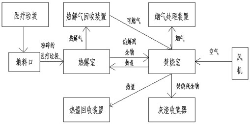
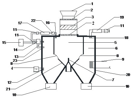
[0022] A pyrolysis incinerator for medical waste, comprising a filling port 1 , a pyrolysis chamber 5 , an incineration chamber 6 , a flue gas purification device 19 , an ash collector 10 , a pyrolysis gas recovery device and a heat recovery device 9 .

[0023] A pulverizer 3 and the pyrolysis chamber 5 are sequentially arranged below the filling port 1, and an openable airtight door 2 is arranged between the pulverizer 3 and the filling port 1, and between the pulverizer 3 and the pyrolysis chamber 5. , the incineration chamber 6 is wrapped around the periphery of the pyrolysis chamber 5, and the heat generated by incineration in the incineration chamber 6 provides working energy for the pyrolysis chamber 5. The bottom of the pyrolysis chamber 5 is provided with a stirring device 7, and on the side wall of the pyrolysis chamber 5 There is a furnace door 8 for pyrolysis residues to be discharged to the incineration chamber 6. The incineration chamber 6 is an inverted concave sh...


PUM


Abstract

A medical waste pyrolysis incinerator comprises a filling port, a pyrolysis chamber, an incineration chamber, a smoke purification device, ash collectors, a pyrolysis gas recovery device and a heat recovery device, a pulverizer and the pyrolysis chamber are sequentially arranged below the filling port, a sealing door is arranged between the pulverizer and the filling port, a sealing door is arranged between the pulverizer and the pyrolysis chamber, and the incineration chamber wraps the periphery of the pyrolysis chamber. A stirring device is arranged at the bottom in the pyrolysis chamber, furnace doors are arranged on the side wall of the pyrolysis chamber, the incineration chamber is in an inverted U shape, and the ash collectors are arranged on protruding parts on the two sides of the incineration chamber. The pyrolysis gas recovery device comprises a dust remover, a cooler, a first draught fan and a flow control device, one end of the dust remover is connected with a pyrolysis gas exhaust port formed in the pyrolysis chamber through a pipeline, the other end of the dust remover is connected with the first draught fan through a pipeline, and pyrolysis gas passes through the pyrolysis gas exhaust port, the first draught fan and a flow control device to introduce gas into the incineration chamber. The medical waste pyrolysis incinerator is clean, environment-friendly, large in treatment capacity, high in thermal efficiency, free of generation of dioxin and other toxic substances and capable of being widely applied.

Description

technical field [0001] The invention relates to the technical field of medical waste treatment, and specifically relates to a medical waste pyrolysis incinerator. Background technique [0002] Medical waste refers to polluting waste produced by medical institutions that have come into contact with patients' blood, skin, etc., such as used disposable medical devices, gauze, cotton balls, postoperative waste, etc. Medical waste is highly polluting, and the viruses and bacteria it carries are dozens, hundreds or even thousands of times more harmful than ordinary domestic waste. If it is not handled correctly, it will cause serious damage to the ecological environment and even lead to infection occurrence of a pandemic. [0003] There are three main categories of traditional medical waste treatment methods: the first category is high-temperature treatment, such as incineration, pyrolysis, gasification, etc.; the second category is alternative treatment, such as chemical disinfe...

Claims


Application Information

Patent Timeline
Patent Type & Authority Applications(China)
IPC IPC(8): F23G7/00F23G5/027F23G5/033F23G5/12F23G5/44F23G5/46F23G5/50F23J15/02
CPCF23G7/00F23G5/0273F23G5/033F23G5/12F23G5/44F23G5/46F23G5/50F23J15/02F23G2201/303F23G2206/10F23G2207/40F23G2209/20
Inventor 刘崇飞王学涛邢利利丁坤李健苏砚鑫唐俊刚
Owner HENAN UNIV OF SCI & TECH
Why Eureka
Try Eureka