
Spraying dust falling and cooling device based on building construction

A technology for building construction and cooling device, applied in construction, using liquid separating agent, road cleaning, etc., can solve problems such as unstable center of gravity, tilting, poor installation adaptability, etc.

Active Publication Date: 2020-10-20
天佳建设集团有限公司
View PDF8 Cites 2 Cited by
  • Summary
  • Abstract
  • Description
  • Claims
  • Application Information

AI Technical Summary

Problems solved by technology

[0005] The object of the present invention is to provide a kind of spraying dust-reducing temperature-reducing device based on building construction, to solve the problem that the existing building-construction cooling and dust-reducing device proposed in the above-mentioned background technology is all fixedly placed on the ground through the base during installation, but this cannot If the whole device is erected too high, otherwise the center of gravity will be unstable and it will be tilted and tilted. Therefore, it cannot be used when high-rise buildings need to cool down and reduce dust. Although some devices can be fixed on the scaffold, the connection structure between these devices and the scaffold The spacing is fixed. If the overall width of the scaffold is different or the width of a certain position in the middle is different, it cannot be fixed, and the installation adaptability is poor.

Method used


Image

  • Spraying dust falling and cooling device based on building construction
  • Spraying dust falling and cooling device based on building construction
  • Spraying dust falling and cooling device based on building construction

Examples


Embodiment Construction

[0026] The following will clearly and completely describe the technical solutions in the embodiments of the present invention with reference to the accompanying drawings in the embodiments of the present invention. Obviously, the described embodiments are only some, not all, embodiments of the present invention.

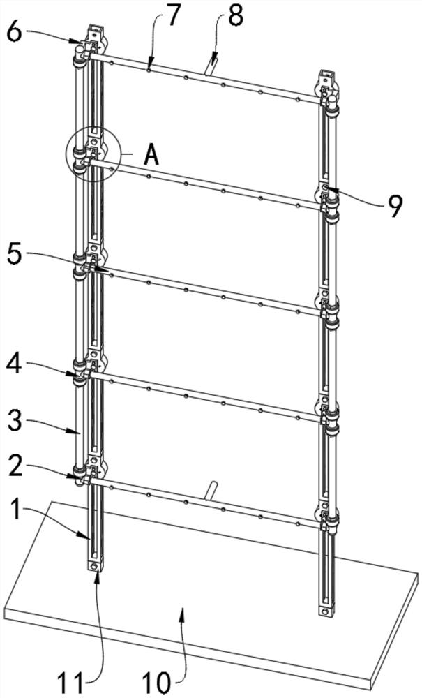
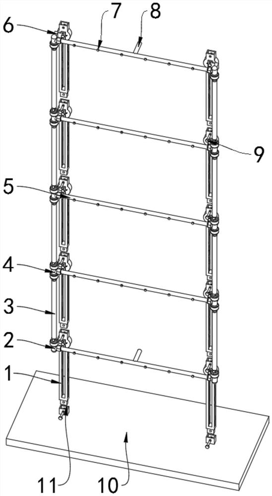
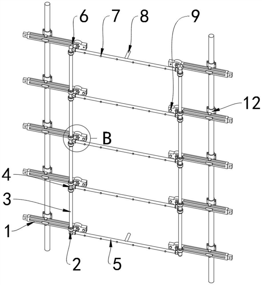
[0027] see Figure 1 to Figure 8, an embodiment provided by the present invention: a device for spraying dust and cooling based on building construction, including a double-way joint 2, a support base plate 10, a No. 1 scaffold connection seat 12 and a No. 2 scaffold connection seat 14; the double-way joint 2 A joint connecting plate 6 is fixedly connected with the rear side of the three-way joint 4; the joint connecting plate 6 is rotationally connected with the support bar 1 through a rotating shaft, and the joint connecting plate 6 and the support bar 1 are also fixed by two screws; The support rod 1 can rotate on the rear side of the joint connecting plate 6, and...


PUM


Abstract

The invention discloses a spraying dust-falling and cooling device based on building construction, relates to the technical field of constructional engineering, and solves the problems that an existing cooling and dust falling device cannot be used in a high-rise building and is poor in installation adaptability. The spraying dust-falling and cooling device comprises a two-way joint and a supporting bottom plate, wherein the rear side of the two-way joint and the rear side of a three-way joint are each fixedly connected with a joint connecting plate; a water inlet pipe is fixedly connected tothe middle of each of the topmost water spraying pipeline and the bottommost water spraying pipeline; the upper and lower adjacent supporting rods are fixedly connected through a group of supporting rod connecting bolts; and two bottom plate connecting blocks are fixedly and symmetrically arranged at the top of the supporting bottom plate. The supporting rods can be fixedly mounted at the top of the supporting bottom plate through the bottom plate connecting blocks, and can also be installed on the front side of a vertical scaffold and the front side of a horizontal scaffold through a first scaffold connecting base and a second scaffold connecting base respectively, and the installation distance can be adjusted at will, so that adjustment and installation can be conducted even if the widthof the scaffold is changed, and the installation adaptability is greatly improved.

Description

technical field [0001] The invention relates to the technical field of construction engineering, in particular to a spray dust suppression and cooling device for construction. Background technique [0002] During the construction of the main structure of the construction project, the working surface is mostly exposed to the scorching sun. In hot summer, the temperature on the construction working surface is very high, sometimes even exceeding 40°C, so that workers have to stagger the high temperature time period when constructing on the scaffolding. Even so, the phenomenon of heatstroke and fainting of workers caused by high temperature during construction operations still occurs from time to time. Therefore, reducing the temperature of the construction work surface and improving the high temperature environment of the construction work surface have become the key factors for people-oriented, green construction and improvement of construction efficiency. In addition, a lot ...

Claims


Application Information

Patent Timeline
IPC IPC(8): E01H3/04B01D47/06
CPCB01D47/06E01H3/04
Inventor 金琰
Owner 天佳建设集团有限公司
Learn More