Display module

A display module and display area technology, which is applied in the direction of optics, instruments, electrical components, etc., can solve the problems of the appearance quality of the display screen, the large width of the frame area, and the effect of splicing display.

Pending Publication Date: 2020-10-20
SHENZHEN CHINA STAR OPTOELECTRONICS TECH CO LTD
View PDF5 Cites 4 Cited by
  • Summary
  • Abstract
  • Description
  • Claims
  • Application Information

AI Technical Summary

Problems solved by technology

Due to the limitations of the bonding process, in panel design, it is usually necessary to bundle the in-plane signal lines through the fan-out area first, concentrate them in a small bonding area, and then bind the COF/FPC to this area, and finally Form an electrical connection between the PCB (...

Method used


Image

  • Display module
  • Display module
  • Display module

Examples


Embodiment Construction

[0022] The following will clearly and completely describe the technical solutions in the embodiments of the present invention with reference to the accompanying drawings in the embodiments of the present invention. Obviously, the described embodiments are only some, not all, embodiments of the present invention. Based on the embodiments of the present invention, all other embodiments obtained by those skilled in the art without creative efforts fall within the protection scope of the present invention.

[0023] In describing the present invention, it should be understood that the terms "center", "longitudinal", "transverse", "length", "width", "thickness", "upper", "lower", "front", " The orientation or positional relationship indicated by "rear", "left", "right", "vertical", "horizontal", "top", "bottom", "inner", "outer", etc. is based on the orientation shown in the drawings Or positional relationship is only for the convenience of describing the present invention and simpl...


PUM


Abstract

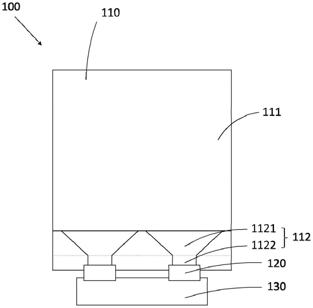
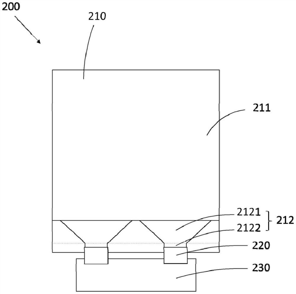
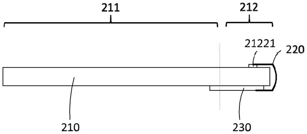
The invention discloses a display module. The display module comprises a display panel which comprises a display region and a frame region disposed at the outer side of the display region, and a plurality of bonding pads are disposed in the frame region; the display module further comprises a printed circuit board and a plurality of binding wires, one ends of the plurality of binding wires are bound on the plurality of bonding pads one by one, and the other ends of the plurality of binding wires are electrically connected with the printed circuit board. According to the display module, the printed circuit board is directly connected with the binding bonding pads on the display panel through the binding wires, so that the width of the frame of the display module is effectively reduced, theappearance effect of the display module is improved, and when the display module is applied to splicing display equipment, smaller splicing seams can be formed.

Description

technical field [0001] The present application relates to the field of display technology, in particular to a display module. Background technique [0002] In the traditional display manufacturing process, it is necessary to input the required signals of the panel into the panel through the module process of COF (Chip On Film) / FPC (Flexible Printed Circuit, flexible circuit board). Due to the limitations of the bonding process, in panel design, it is usually necessary to bundle the in-plane signal lines through the fan-out area first, concentrate them in a small bonding area, and then bind the COF / FPC to this area, and finally Form an electrical connection between the PCB (Printed Circuit Board, printed circuit board) and the glass substrate, so that the width of the border area is larger, which has a greater impact on the appearance of the display screen. If it is used for splicing screens, There will be obvious patchwork, which will affect the effect of splicing display...

Claims


Application Information

Patent Timeline
IPC IPC(8): G02F1/1345G09F9/30G09F9/33G09F9/35H01L27/32
CPCG02F1/1345G02F1/13458G02F1/13452G09F9/30G09F9/33G09F9/35H10K59/10
Inventor 徐健
Owner SHENZHEN CHINA STAR OPTOELECTRONICS TECH CO LTD
Why Eureka
Try Eureka