Cable interface quick binding device for hydroelectric power generation

A technology of cables and interfaces, which is applied in the field of fast binding devices for cable interfaces used in hydropower generation, and can solve problems such as low binding and fixing efficiency

Active Publication Date: 2020-10-20
山西万家寨水控水利机电科技服务有限公司
View PDF8 Cites 0 Cited by
  • Summary
  • Abstract
  • Description
  • Claims
  • Application Information

AI Technical Summary

Problems solved by technology

[0004] Based on the technical problem of low binding and fixing efficiency of the existing fast binding device for cable interface for hydropower generation, the present invention proposes a quick binding device for cable interface for hydropower generation

Method used


Image

  • Cable interface quick binding device for hydroelectric power generation
  • Cable interface quick binding device for hydroelectric power generation
  • Cable interface quick binding device for hydroelectric power generation

Examples


Embodiment 1

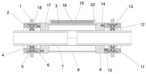
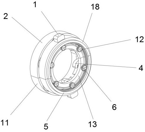
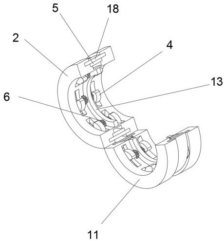
[0027] refer to Figure 1-3 and Figure 5 , a fast binding device for a cable interface for hydroelectric power generation, comprising a clamp ring 2, the bottom of the clamp ring 2 is connected with a clamp ring 11 through a hinge, and the inner walls of the clamp ring 2 and the clamp ring 11 are fixed by bolts. Half ring 13, fixed half ring 13 is fixed with clamping mechanism, and clamp ring one 2 and clamp ring two 11 inwalls all are connected with semicircle slide plate 18 by sliding, and semicircle slide plate 18 fixed rotation mechanism, offers in clamp ring one 2 side walls A card slot 14, a buckle 10 is inserted into the wall of the card slot 14, and the buckle 10 is fixed with a wrapping mechanism.

[0028] Among the present invention, clamping mechanism comprises rotating shaft one 12, and rotating shaft one 12 is connected with fixed semi-ring 13 by bearing, and rotating shaft one 12 outer wall is sleeved with gear 6, and rotating shaft one 12 outer wall both sides...

Embodiment 2

[0035] refer to Figure 4 and Figure 5 , a cable interface fast binding device for hydroelectric power generation. Compared with Embodiment 1, the glue supply mechanism of this embodiment includes the second rotating shaft 16, the second rotating shaft 16 is connected to the support plate 20 through bearings, and the outer wall of the second rotating shaft 16 is sleeved with Tape post15.

[0036] In the present invention, the gluing mechanism includes a chute plate 23, the chute plate 23 and the inner wall of the rotating plate 3 are connected by bolts, the chute plate 23 is inserted with a pressure plate 21, and the pressure plate 21 and the inner wall of the chute plate 23 are connected by bolts. A spring is connected, and the bottom outer wall of the pressing plate 21 is connected with a rotating post 22 by bolts.

[0037]During use, when the rotating plate one 3 rotates, the rotating column 22 rotates accordingly, and the pressing plate 21 presses the tape to the inner ...


PUM


Abstract

The invention discloses a cable interface quick binding device for hydroelectric power generation. Aimed at problems of low speed for binding and complex operation, the following scheme is provided. The device comprises a first clamping ring, the bottom of the first clamping ring is connected with a second clamping ring through a hinge. Fixing semi-rings are connected to the inner walls of the first clamping ring and the second clamping ring through bolts, clamping mechanisms are fixed to the fixing semi-rings, semicircular sliding plates are slidably connected to the inner walls of the firstclamping ring and the second clamping ring, rotating mechanisms are fixed to the semicircular sliding plates, a clamping groove is formed in one side wall of the first clamping ring, and a buckle is inserted into the wall of the clamping groove. When in use, the rotating handle is rotated, the semicircular toothed plate rotates to drive the gear to rotate, the rubber clamping teeth in the first clamping ring and the second clamping ring rotate to clamp a cable, the cables on the two sides are fixed, the fixing degree is increased along with increase of the rotating angle of the semicircular toothed plate, the device can fix the cables of different thicknesses more stably and is not affected by the thickness of the cables, and the flexibility of the device is remarkably improved.

Description

technical field [0001] The invention relates to the technical field of cable fixing, in particular to a fast cable interface binding device for hydropower generation. Background technique [0002] A cable is usually a rope-like cable twisted by several or groups of conductors (at least two in each group). Each group of conductors is insulated from each other and is often twisted around a center. Highly insulating overlay. The cable has the characteristics of internal energization and external insulation. During the process of hydropower generation, when the cable is accidentally broken, it needs to be re-bonded and reorganized. A quick-binding device for the cable interface is needed to instantly bind and put it into use quickly. [0003] The existing fast binding device for cable interface for hydropower generation is not fast enough, the structure is more complicated, the operation is more troublesome, the efficiency of interface binding is reduced, and the work burden of...

Claims


Application Information

Patent Timeline
Patent Type & Authority Applications(China)
IPC IPC(8): H02G15/08F16L3/10
CPCH02G15/08F16L3/1075
Inventor 李效东
Owner 山西万家寨水控水利机电科技服务有限公司
Why Eureka
Try Eureka