A method for testing the message output performance of a digital relay protection tester

A relay protection and output performance technology, applied in digital transmission systems, emergency protection circuit devices, electrical components, etc., can solve the problems of imperfect testing safety, incomplete testing, incomplete testing, etc., and achieve a wide range of applications, The effect of reducing workload and reducing safety hazards

Active Publication Date: 2021-11-09
STATE GRID SICHUAN ELECTRIC POWER CORP ELECTRIC POWER RES INST
View PDF12 Cites 0 Cited by
  • Summary
  • Abstract
  • Description
  • Claims
  • Application Information

AI Technical Summary

Problems solved by technology

[0006] The technical problem to be solved by the present invention is: the existing test for checking the output capability of the digital relay protection tester is incomplete, the test is not comprehensive, the coverage rate is low, and the test safety is not perfect

Method used


Image

  • A method for testing the message output performance of a digital relay protection tester
  • A method for testing the message output performance of a digital relay protection tester
  • A method for testing the message output performance of a digital relay protection tester

Examples


Embodiment 1

[0056] The present invention provides a method for testing the message output performance of the digital relay protection tester. The digital relay protection tester is connected to an optical switch, and the other multi-ports of the optical switch are connected to fault recording and network message recording and analysis devices. .

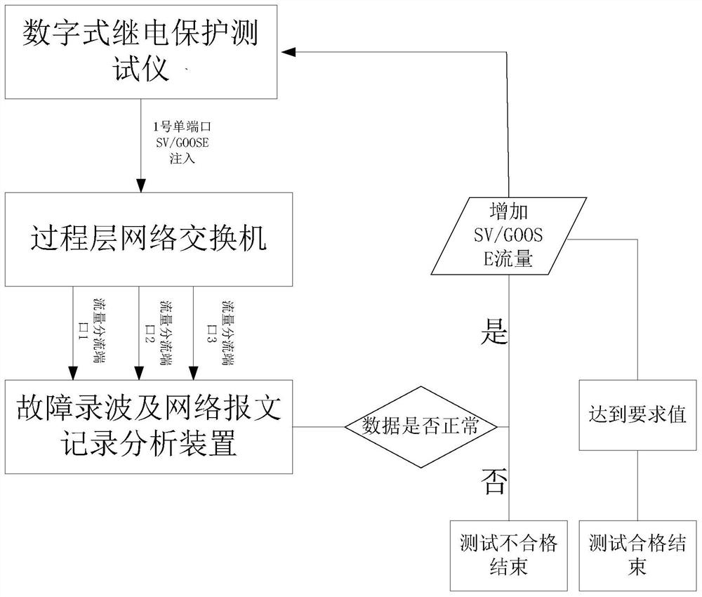
[0057] Such as figure 1 The schematic diagram of the single-port message output performance test of the digital relay protection tester is shown in the schematic diagram, and the wiring methods of each port are as follows: Figure 4

[0058] When the digital relay protection tester outputs single-port messages, the performance test steps specifically include:

[0059] S1. Import the SCD file configured in the smart substation into the tester, and respectively import SV and GOOSE messages at different intervals, so as to simulate the process layer messages of the smart substation. Configure multiple VLANs through the tester. For example, confi...

Embodiment 2

[0068] The digital relay protection tester is connected with the optical switch, and the other multi-ports of the optical switch are connected with the fault recording and network message recording and analysis device.

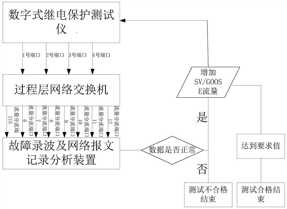
[0069] The multi-port message output capability test can effectively test the abnormality and fault capability of the digital relay protection tester itself in the substation debugging process, so as to be safe and stable after subsequent on-site operation. This test method can fill the multi-port message flow to the maximum value of the tester's allowable output flow, and carry out various abnormal message capability simulations and various short-circuit fault simulations under the condition of large flow output, which is beneficial to the real simulation of each substation. A smart device simulates sudden network incidents. in, figure 2 It is a schematic diagram of a digital relay protection multi-port message output performance test of the present inventi...

Embodiment 3

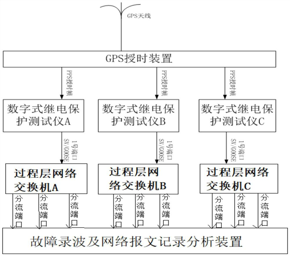
[0081] The synchronization function test of multiple testers can mainly be used to verify the data synchronization test function of the channel test on both sides of the smart substation line or on the three sides of the line, and can effectively verify the optical difference channel of the line protection.

[0082]The verification of protection functions on both sides and three sides of the line often cannot be tested by injecting digital quantities through a tester, and can only be verified by GPS accurate time synchronization, so that synchronous triggering can be performed through GPS devices on both sides of the line. By checking the data synchronization on the fault recording and network message recording and analysis device, verify whether the SV, GOOSE and other data are triggered synchronously.

[0083] image 3 Wiring diagram for synchronous function test of multiple digital relay protection testers;

[0084] Step 1: Import the SCD files configured in the smart subs...


PUM


Abstract

The invention discloses a method for testing the message output performance of a digital relay protection tester. VLANs are evenly distributed in the digital relay protection tester and an optical switch, so that fault recording and network message recording and analysis devices can analyze data more accurately; The tester multi-port configuration different message data is output from the tester port at the same time, injected into the optical switch through the increase of traffic, and more output ports are adopted on the output side of the optical switch to the fault recording and network message recording and analysis device and assigned VLANs, so that The device for fault recording and network message recording and analysis can analyze data more accurately. When the flow reaches the limit state of the output of the tester, it can simulate the ability to output various abnormal messages with large flow rate and simulate various short-circuit faults; the invention provides multiple testers The synchronous test method uses GPS to accurately synchronize the time synchronization trigger to verify the synchronization function. By checking the data synchronization on the fault recording and network message recording and analysis device, check whether the message data is triggered synchronously.

Description

technical field [0001] The invention relates to the technical field of power system protection and debugging, in particular to a method for testing the message output performance of a digital relay protection tester. Background technique [0002] The digital relay protection instrument is an important equipment for the protection and debugging of today's smart substations. The digital relay protection instrument can be an important tool for debugging the process level equipment of the smart substation, and can test various digital measurement, control and protection units that comply with the IEC61850 standard specification, and can simulate the instantaneous, permanent, and conversion properties of single-phase to three-phase Faults can be tested as a whole group, multi-phase current can be conveniently tested for three-phase differential protection, and can be used for backup and automatic switching tests, etc. For multiple test equipment, it can also be used for channel t...

Claims


Application Information

Patent Timeline
Patent Type & Authority Patents(China)
IPC IPC(8): H04L12/26H02H7/26
CPCH02H7/261H04L43/50
Inventor 刘学文王大兴钟威黄迎熊亮蒋成敏
Owner STATE GRID SICHUAN ELECTRIC POWER CORP ELECTRIC POWER RES INST
Why Eureka
Try Eureka