Metal plate processing clamping device for constructional engineering

A technology of metal plates and construction engineering, applied in the direction of workpiece clamping devices, manufacturing tools, etc., can solve problems such as troubles and increase equipment use costs

Inactive Publication Date: 2020-10-23
杨庆美
View PDF0 Cites 1 Cited by
  • Summary
  • Abstract
  • Description
  • Claims
  • Application Information

AI Technical Summary

Problems solved by technology

Metal plates for construction engineering need to be clamped during the process of processing, but the existing metal processing clamping devices for construction engineering can usually only clamp and fix metal plates of one size. For metal plates of different sizes , you need to use different clamping equipment, which is not only troublesome, but also increases the cost of using the equipment

Method used


Image

  • Metal plate processing clamping device for constructional engineering
  • Metal plate processing clamping device for constructional engineering
  • Metal plate processing clamping device for constructional engineering

Examples


Embodiment 1

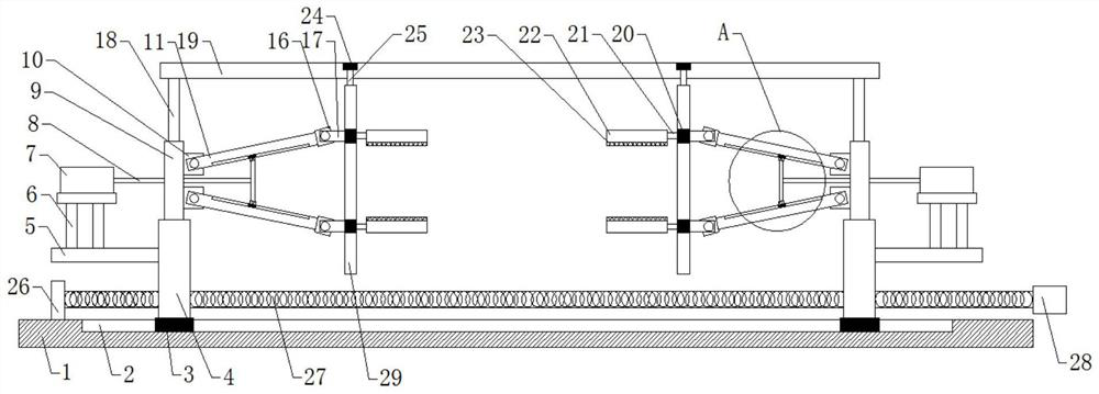
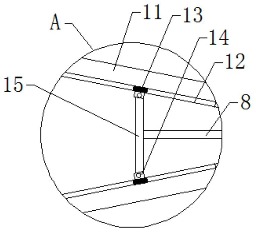
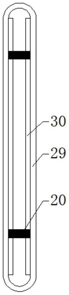
[0021] see Figure 1~4 , in an embodiment of the present invention, a metal plate processing and clamping device for construction engineering includes a workbench 1, a first chute 2 is opened on the upper surface of the workbench 1, and two a first slider 3, the upper sides of the two first sliders 3 are respectively fixedly equipped with a moving plate 4, the upper side of the moving plate 4 is fixedly installed with a fixed plate 9, and the two fixed plates 9 are close to each other Two fixed blocks 10 are respectively fixedly installed on one side, and a transmission rod 11 is connected with rotation on the fixed block 10, and an installation block 16 is fixedly connected with the end of the transmission rod 11 away from the fixed block 10, and the installation block 16 is rotated A connecting rod 17 is connected, and the end of the connecting rod 17 away from the mounting block 16 is fixedly connected with a third slider 20, and the third slider 20 is slidably arranged in ...

Embodiment 2

[0028] see figure 1 , in order to facilitate the adjustment of the distance between the two moving plates 4 in the clamping device for processing metal plates for construction engineering of the present invention, this embodiment has been further improved on the basis of Embodiment 1, and the improvements are: the two described Threaded holes are provided on the moving plate 4 respectively, and the same screw rod 27 matched with the two threaded holes is pierced in the two threaded holes; Bearing seat 26 is arranged, and described screw mandrel 27 left ends are rotatably installed in bearing seat 26, and described screw mandrel 27 right-hand ends are fixedly installed with the handle 28 that screw mandrel 27 is rotated.

[0029] The working principle of the present invention is:

[0030] When using the metal plate processing clamping device for construction engineering of the present invention, first adjust the distance between the two moving plates 4 according to the length ...


PUM


Abstract

The invention discloses a metal plate processing clamping device for constructional engineering, relates to the technical field of constructional engineering, and mainly aims to solve the problem thatthe existing metal plate processing clamping device cannot fix metal plates with different sizes. The metal plate processing clamping device comprises a working table; a first sliding chute is formedin the upper surface of the working table; two first sliding blocks are arranged in the first sliding chute; movable plates are fixedly mounted on the upper sides of the two first sliding blocks separately; a fixed plate is fixedly mounted on the upper side of each of the movable plates; two fixed blocks are mounted on one side of each of the fixed plates; a driving rod is connected onto each ofthe fixed blocks; a mounting block is fixedly connected with the end, far away from each of the fixed blocks, of the driving rod; a connecting rod is rotatably connected with the mounting block; a fixed rod is fixedly connected with the end, far away from the mounting block, of the connecting rod; and the fixed rod is arranged in a positioning mechanism mounted above the working table in a slidingmanner.

Description

technical field [0001] The invention relates to a construction engineering device, in particular to a metal plate processing and clamping device for construction engineering. Background technique [0002] Metal plates are often used in construction projects. Metal plates are used as raw materials in construction projects and have a wide range of uses. According to different uses, the size requirements of metal plates are also different. Metal plates for construction engineering need to be clamped during the process of processing, but the existing metal processing clamping devices for construction engineering can usually only clamp and fix metal plates of one size. For metal plates of different sizes , Need to use different clamping equipment, which is not only troublesome, but also increases the cost of using the equipment. Contents of the invention [0003] The object of the present invention is to provide a clamping device for metal plate processing for construction eng...

Claims


Application Information

Patent Timeline
Patent Type & Authority Applications(China)
IPC IPC(8): B25B11/00
CPCB25B11/00
Inventor 杨庆美
Owner 杨庆美
Why Eureka
Try Eureka