Protective device for medical test tube transportation

A protective device and test tube technology, which is applied in the medical field and can solve the problems of insufficient protection for medical test tube transportation and fragile test tubes

Inactive Publication Date: 2020-10-23
李越强
View PDF0 Cites 3 Cited by
  • Summary
  • Abstract
  • Description
  • Claims
  • Application Information

AI Technical Summary

Problems solved by technology

[0003] But the test tube is fragile, and the existing medical test tubes are all placed in the box directly with the test tube placement box with the medical pipeline during transportation, and a soft pad is usually set at the bottom of the box for protection, but this protective ...

Method used


Image

  • Protective device for medical test tube transportation
  • Protective device for medical test tube transportation
  • Protective device for medical test tube transportation

Examples


Embodiment 1

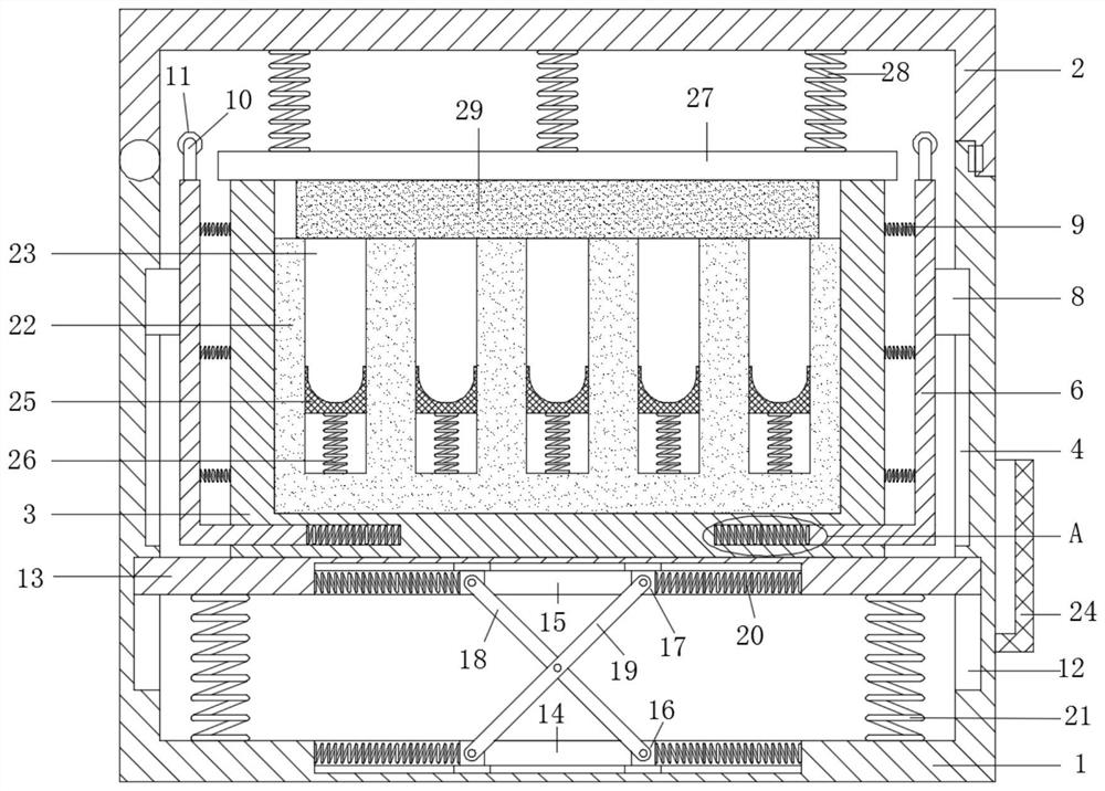
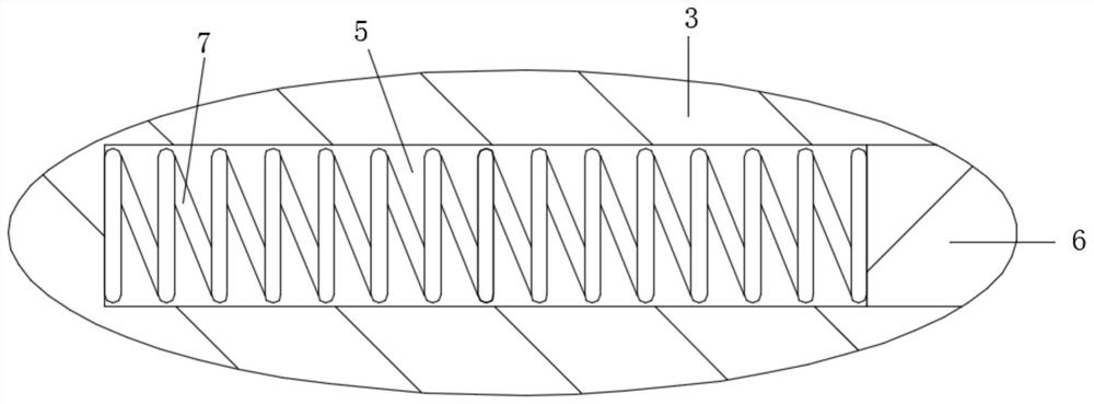
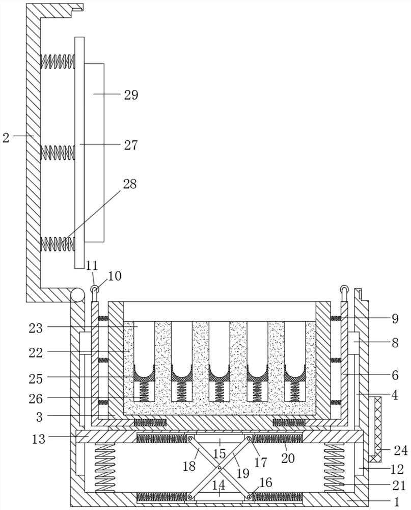
[0021] see Figure 1-3 , a protective device for transporting medical test tubes, comprising a protective frame 1, a protective cover plate 2 with a damping rotation mounted on the protective frame 1, a shock-absorbing protective assembly arranged under the inner part of the protective frame 1, and a test tube with an open mouth Placement frame 3 and test tube placement protection assembly, the test tube placement frame 3 is arranged on the shock-absorbing protection assembly, the test tube placement protection assembly is arranged in the test tube placement frame 3, the test tube placement frame 3 and the side inner wall of the protection frame 1 A horizontal protective assembly is arranged between them, and a chute 4 is symmetrically opened on the side inner wall of the protective frame 1 above the shock-absorbing protective assembly, and a chute 4 is symmetrically opened under the outer wall of the test tube placement frame 3 opposite to the chute 4 . Blind groove 5, the tr...

Embodiment 2

[0029]This embodiment is further improved on the basis of the embodiment, and the improvement is that: the test tube placement groove 23 is provided with a pop-up assembly, and the inner wall of the protective cover 2 is provided with a pressing assembly that cooperates with the pop-up assembly, The pop-up assembly includes a test tube stop block 25 slidably installed in the test tube placement groove 23, and a fifth tension spring 26 is connected between the test tube stop block 25 and the bottom inner wall of the test tube placement groove 23; Plywood 27, a number of evenly distributed sixth extension springs 28 are connected between the pressboard 27 and the inner wall of the protective cover plate 2, and an elastic limit pressing block 29 is arranged on the sidewall of the pressboard 27 facing the test tube placement groove 23 side ; By arranging the test tube limit block 25 and the pressing plate 27, under the joint action of the fifth extension spring 26, the elastic limi...


PUM


Abstract

The invention discloses a protective device for medical test tube transportation. The protective device for medical test tube transportation comprises a protective frame, a protective cover plate, a shock-absorbing protective assembly, a test tube placing frame and a test tube placing protective assembly, wherein a transverse protective assembly is arranged between the test tube placing frame andthe inner wall of the side surface of the protective frame, the transverse protective assembly comprises an L-shaped protective plate, a tension spring is connected between the end part of the L-shaped protective plate and the inner wall of a blind groove, a sliding block matched with a sliding groove is fixedly arranged on the side wall of the L-shaped protective plate, and a second tension spring is connected between the side wall of the L-shaped protective plate and the side wall of the test tube placing frame. The protective device for medical test tube transportation is provided with theL-shaped protective plate, under the action of the tension spring and the second tension spring, the test tube placing frame achieves the purpose of transverse buffering and shock absorption while vertical shock absorption is formed by the shock-absorbing protective assembly, multiple protection on medical test tubes is achieved under the combined action of the test tube placing protective assembly, and the probability of damage to the medical test tubes in the transportation process is further reduced.

Description

technical field [0001] The invention relates to the medical field, in particular to a protective device for transporting medical test tubes. Background technique [0002] Medical test tubes are also commonly used in medical devices, by using medical test tubes to store some solutions or samples. [0003] But the test tube is fragile, and the existing medical test tubes are all placed in the box directly with the test tube placement box with the medical pipeline during transportation, and a soft pad is usually set at the bottom of the box for protection, but this protective measure can only be realized in The shock absorption protection in the vertical direction has the problem that the transportation protection of medical test tubes is not in place. Based on this, we propose a protective device for medical test tube transportation to solve the above problems. Contents of the invention [0004] The object of the present invention is to provide a protective device for trans...

Claims


Application Information

Patent Timeline
IPC IPC(8): B65D25/10B65D81/07B65D25/06
CPCB65D25/06B65D25/10B65D81/07
Inventor 李越强
Owner 李越强
Why Eureka
Try Eureka