
Shaft part bounce detection mechanism and detection method capable of automatically eliminating spindle errors

A technology for runout detection and shaft parts, which is used in measuring devices, instruments, etc., and can solve problems such as difficult detection accuracy, control, and influence on equipment accuracy.

Pending Publication Date: 2020-10-23
杭州集智机电股份有限公司 +2
View PDF0 Cites 8 Cited by
  • Summary
  • Abstract
  • Description
  • Claims
  • Application Information

AI Technical Summary

Problems solved by technology

If the fixture is not repaired and replaced for a long time, it will greatly affect the accuracy of the equipment
And using the above method, it is also difficult to control the detection accuracy to be better than 1 micron

Method used


Image

  • Shaft part bounce detection mechanism and detection method capable of automatically eliminating spindle errors
  • Shaft part bounce detection mechanism and detection method capable of automatically eliminating spindle errors
  • Shaft part bounce detection mechanism and detection method capable of automatically eliminating spindle errors

Examples


Embodiment Construction

[0036] The present invention will be further described below in conjunction with the accompanying drawings and specific implementation.

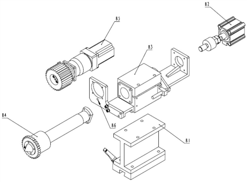
[0037] like figure 1 figure 2 As shown, the specific implementation of the present invention includes a supporting mechanism A0, a driving side clamping driving part B0, a driven side clamping driving part C0, a runout detection mechanism D0 and a workpiece E0. The two supporting mechanisms A0 are fixed on the machine base by screws, and the workpiece E0 is placed on the two supporting mechanisms A0 for subsequent detection and alignment steps; the driving part is clamped by the driving part B0 and the driven part is clamped by the driven side C0 is located on the left and right sides of the workpiece E0 and is fixed on the machine base, and is also located on both sides of the two support mechanisms A0; the clamping cylinder B2 of the active side clamping the driving part B0 and the clamping cylinder B2 of the driven side clamping the dri...


PUM


Abstract

The invention discloses a shaft part bounce detection mechanism and a detection method capable of automatically eliminating spindle errors. Two supporting mechanisms are fixed to a machine base through screws, and a workpiece is placed on the two supporting mechanisms. Driving and driven side clamping driving components are located on the left side and the right side of the workpiece correspondingly and fixed to the machine base; the driving and driven side clamping driving components are pushed out and clamped at the two ends of the workpiece through live centers, so that the workpiece is clamped and driven to rotate around the axis of the workpiece to do rotary motion; through pushing out of clamping air cylinders, the live centers clamp the workpiece, and the servo motor drives the centers to enable the workpiece to do rotary motion around the axis of the workpiece; and the bounce detection mechanism is installed beside the workpiece and detects surface bounce of the workpiece in the rotating process. According to the invention, the rotation run-out detection precision of shaft parts is improved; and on the premise that the production efficiency of equipment is not reduced and the detection precision is not sacrificed, the requirements of an equipment tool clamp and the production and use cost are reduced.

Description

technical field [0001] The invention relates to a rotation detection mechanism and detection method of shaft parts, in particular to a mechanical structure and a detection method for eliminating the influence of tip / spindle beating on the test during the detection process. Background technique [0002] Shaft parts have runout requirements during assembly with other parts. Shaft parts generally need to go through rough turning, finishing turning, grinding and other steps. These process steps also have runout requirements for the parts to be processed. Straightening equipment is an automatic equipment that automatically straightens shaft parts to make their runout meet the technical requirements. The general action flow of the straightening equipment is to detect the rotary runout of the workpiece, and then perform pressure cold / flame heat straightening, and repeat the above steps until the final re-inspection meets the qualified requirements. [0003] Runout detection is a ...

Claims


Application Information

Patent Timeline
Patent Type & Authority Applications(China)
IPC IPC(8): G01B21/00
CPCG01B21/00
Inventor 翁嘉豪袁春华姚凯强沈捷何珊储佳佳
Owner 杭州集智机电股份有限公司
Learn More