
Flight speed and trajectory joint optimization method and system

A flight speed and joint optimization technology, which is applied in general control systems, control/regulation systems, non-electric variable control, etc., can solve problems such as inapplicable mass data transmission and poor system information throughput

Active Publication Date: 2020-10-23
NANTONG UNIVERSITY
View PDF4 Cites 7 Cited by
  • Summary
  • Abstract
  • Description
  • Claims
  • Application Information

AI Technical Summary

Problems solved by technology

However, when the UAV flies on a straight track, the communication system will have an upper limit of information throughput, which means that the straight track is not suitable for a large amount of data transmission; when the UAV flies on a circular track, if the source node The distance between the destination node and the destination node is long, the information throughput of the system will be poor

Method used


Image

  • Flight speed and trajectory joint optimization method and system
  • Flight speed and trajectory joint optimization method and system
  • Flight speed and trajectory joint optimization method and system

Examples


Embodiment approach

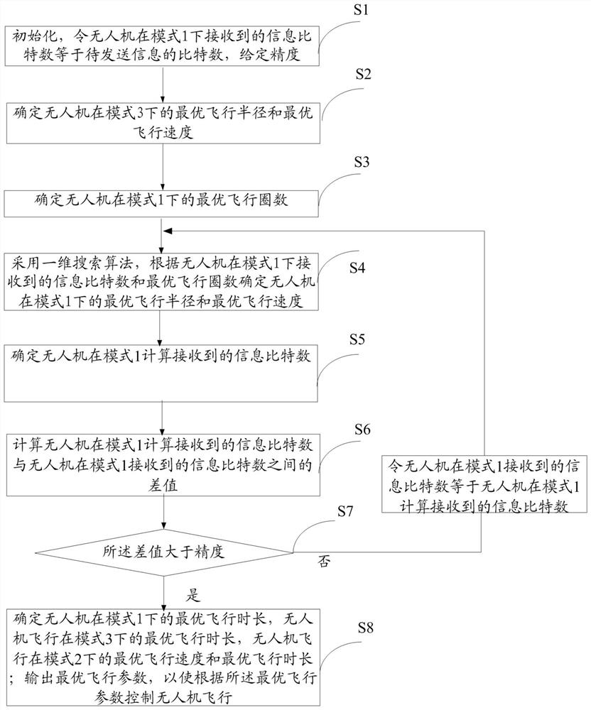
[0183] As an embodiment, the method of the present invention also includes:

[0184] Step S9: Calculate the minimum flight total energy consumption according to the optimal flight parameters, the specific formula is:

[0185]

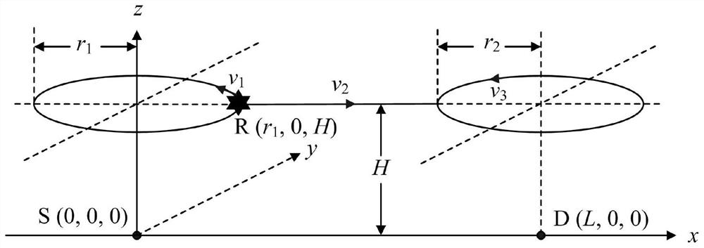
[0186] Among them, E is the minimum total flight energy consumption, g is the acceleration of gravity, c 1 =ρC D0 S / 2 and c 2 = 2W 2 / [(πe 0 A R )ρS], ρ means air density, C D0 Indicates zero-lift drag coefficient, S indicates wing area, e 0 is the wingspan efficiency, W represents the overall weight of the UAV, and A R represents the aspect ratio of the drone's wing, and are the optimal flight radius, optimal flight speed, and optimal flight duration of the UAV in mode 1, respectively, and are the optimal flight speed and optimal flight time of UAV flying in mode 2, respectively, and are the optimal flight radius, optimal flight speed, and optimal flight duration of UAV flying in mode 3, respectively.

[0187]Step S1: Initialize,...


PUM


Abstract

The invention discloses a flight speed and trajectory joint optimization method and system. The method comprises the steps: determining the optimal flight circle number, optimal flight radius and optimal flight speed of an unmanned plane in a mode 1, and enabling the unmanned plane to calculate the received information bit number and difference in the mode 1; judging whether the difference value is greater than precision; if so, enabling the bit number of the information calculated and received by the unmanned aerial vehicle in the mode 1 to be equal to the bit number of the information received by the unmanned aerial vehicle in the mode 1, and re-determining the optimal flight radius and the optimal flight speed of the unmanned aerial vehicle in the mode 1; otherwise, determining the optimal flight duration of the unmanned aerial vehicle in the mode 1, the optimal flight duration of the unmanned aerial vehicle in the mode 3, and the optimal flight speed and the optimal flight durationof the unmanned aerial vehicle in the mode 2; and controlling the unmanned aerial vehicle to fly according to the optimal flight parameters. According to the bit number of the information to be transmitted of the source node and the distance between the source node and the destination node, the flight speed and the flight trajectory of the unmanned aerial vehicle relay node are jointly adjusted.

Description

technical field [0001] The invention relates to the technical field of unmanned aerial vehicle control, in particular to a joint optimization method and system for flight speed and trajectory. Background technique [0002] In recent years, UAV cooperative communication technology has become a research hotspot in the field of wireless communication. Compared with traditional ground communication, UAV cooperative communication is easy to realize on-demand distribution, which is more cost-effective; UAV is highly mobile, so it is more flexible and quick to deploy; UAV and ground terminal Most of the channel links are line-of-sight links, which can provide a better channel environment. Therefore, drones will play an extremely important role in the future wireless communication field, and its applications mainly include: (1) as a temporary base station; (2) as a mobile relay; (3) for the Internet of Things. [0003] At present, a large number of literatures have studied the opt...

Claims


Application Information

Patent Timeline
IPC IPC(8): G05D27/02G05B13/04
CPCG05B13/042G05D27/02
Inventor 吉晓东钱冲李文华
Owner NANTONG UNIVERSITY
Learn More