Externally-hung type heat dissipation system for graphics card

A heat dissipation system and plug-in technology, applied in the direction of instruments, electrical digital data processing, digital data processing components, etc., can solve the problems of affecting the heat dissipation effect of the graphics card, it is difficult to determine the root of the problem, and the speed is reduced.

Inactive Publication Date: 2020-10-23
LAIWU VOCATIONAL & TECHNICAL COLLEGE
View PDF0 Cites 0 Cited by
  • Summary
  • Abstract
  • Description
  • Claims
  • Application Information

AI Technical Summary

Problems solved by technology

The most common situation is that the speed decreases due to aging, which directly affects the heat dissipation effect of the graphics card, thus affecting the life of the graphics card
[0004] However, the graphics card is a component with a high degree of integration, and it is difficult for ordinary users

Method used


Image

  • Externally-hung type heat dissipation system for graphics card
  • Externally-hung type heat dissipation system for graphics card
  • Externally-hung type heat dissipation system for graphics card

Examples


Embodiment 1

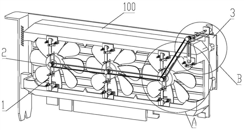
[0046] see Figure 1 to Figure 5 , the present invention provides a graphics card plug-in heat dissipation system, including a connection part 1 hooked on one side of the graphics card fan 100, the connection part 1 is fixedly connected to the outer cover of the graphics card fan 100, the connection part 1 is connected to the driven assembly 2, from The moving assembly 2 is linked with the driving part 3;

[0047] The driven assembly 2 includes a pressing plate 21 . The pressing plate 21 abuts against the outer middle part of the central shaft housing of the graphics card fan 100 . The driving part 3 drives the pressing plate 21 to rotate.

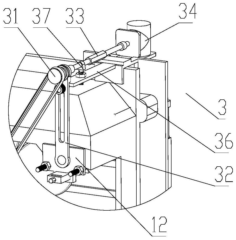
[0048] The side of the pressure plate 21 far away from the graphics card fan 100 is fixedly connected to the pressure plate shaft, and the driven pulley 22 is fixedly arranged on the pressure plate shaft. In conjunction, the drive unit 3 is disposed on the side of the graphics card away from the graphics card fan 100 .

[0049] The press...

Embodiment 2

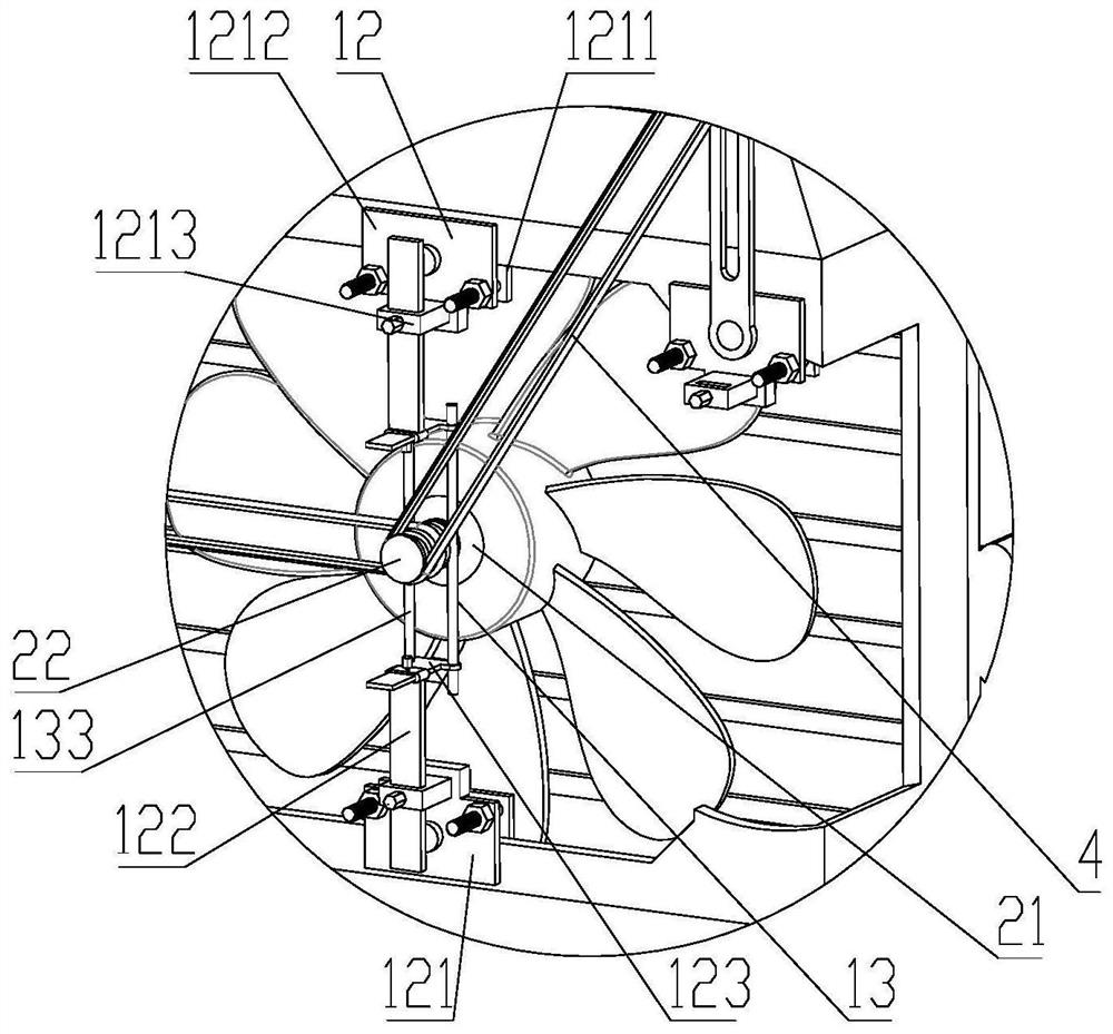
[0053] On the basis of Embodiment 1, the connection part 1 includes a fixed plate group 12, one end of the fixed plate group 12 is fixedly connected to the outer cover of the graphics card fan 100, and the other end is connected to the pressure plate shaft of the pressure plate 21, and each graphics card fan 100 is at least Corresponding to two fixed plate groups 12;

[0054] The fixing plate group 12 includes a cover fixing unit 121 fixedly connected to the outer cover body of the graphics card fan 100. The cover fixing unit 121 is connected to one end of a jumper plate 122. The jumper plate 122 extends towards the axial direction of the graphics card fan. One end of the jumper plate 122 It is fixedly connected with the cover fixing unit 121, and the other end is connected with the clamp rod fixing plate 123;

[0055] The pressure plate 21 is connected with the clamping rod group 13, and the clamping rod group includes a thrust bearing 131 and a radial bearing 132 sequentiall...

Embodiment 3

[0060] On the basis of the above embodiments, a through groove is opened on the cover fixing unit 121, and the cover fixing unit 121 is slidingly connected with the bridging plate 122 through the through groove, and the connection between the cover fixing unit 121 and the bridging plate 122 is locked by locking bolts , the jumper board 122 is parallel to the circuit board of the graphics card;

[0061] One end of the clamping rod fixing plate 123 plate body is fixedly connected with the clamping rod 133, and is slidably connected with the bridging plate 122, and the connection between the clamping rod fixing plate 123 and the bridging plate 122 is locked by a locking bolt;

[0062] Taking the insertion direction of the graphics card and the computer motherboard as the vertical direction, the jumper plate 122 is vertically arranged, the through groove of the cover fixing unit 121 is a vertical through groove, and the jumper plate 122 passes through the through groove of the cove...


PUM


Abstract

The invention relates to the field of computer equipment, and discloses an externally-hung type heat dissipation system for a graphics card. The system comprises a connecting part hung on one side ofa graphics card fan; the connecting part is fixedly connected with an external cover body of the graphics card fan; the connecting part is connected with a driven assembly; the driven assembly is in linkage with a driving part; the driven assembly comprises a pressing plate; the pressing plate abuts against the middle of the outer side of a graphics card fan middle shaft shell; and the driving part drives the pressing plate to rotate. The externally-hung type assembly can be matched with most of graphics cards, good adaptability is achieved; the assembly can be additionally arranged under thecondition that related assemblies of the graphics card fan are aged, driving force is provided for the graphics card fan from the outside, and therefore the heat dissipation effect of the graphics card is guaranteed. According to the technical schemes of the invention, the overall cost is low, and no large cost consumption is brought to fan maintenance.

Description

technical field [0001] The invention relates to the field of computer equipment, in particular to an external cooling system for a graphics card. Background technique [0002] The graphics card is one of the most basic components of a computer. Its purpose is to convert the display information required by the computer system to drive the display, and to provide progressive or interlaced scanning signals to the display to control the correct display of the display. It is the connection between the display and the motherboard of the personal computer. An important component is one of the important devices of "man-machine". Its built-in parallel computing capability is also used for deep learning and other operations at this stage. [0003] For designing a computer with a high demand for graphics operations, it is often necessary to configure a high-performance graphics card. The price of a high-performance graphics card ranges from 1000 yuan to more than 10,000 yuan. The grap...

Claims


Application Information

Patent Timeline
IPC IPC(8): G06F1/20
CPCG06F1/20
Inventor 焉凯刘霞
Owner LAIWU VOCATIONAL & TECHNICAL COLLEGE
Why Eureka
Try Eureka