

Dangerous chemical safety inspection device and gate system
A hazardous chemical and security inspection technology, which is applied in the field of gate systems and hazardous chemical security inspection devices, can solve the problems of large consumption of test paper and high sampling cost
- Summary
- Abstract
- Description
- Claims
- Application Information
AI Technical Summary
Problems solved by technology
Method used
Image

Examples
no. 1 approach
[0017] The first embodiment of the present invention provides a dangerous chemical security inspection device. The hazardous chemical security inspection device collects and detects hazardous chemicals.
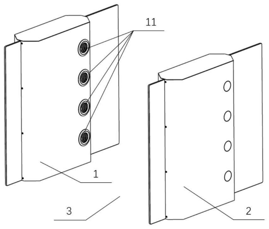
[0018] The dangerous chemical security inspection device 100 includes a first body 1 and a second body 2 . The first body 1 and the second body 2 are arranged opposite to each other at a certain distance to form a security inspection channel 3 . Here, a certain interval is the width of the security inspection channel 3, which can be set arbitrarily as required. The left and right positions of the first body 1 and the second body 2 relative to the security inspection channel 3 are also not limited.
[0019] The dangerous chemical security inspection device here can be implemented, for example, by means of a security inspection door, and the security inspection door also has a part connecting the tops of the first body 1 and the second body 2 . The specific shape and result ...
Embodiment 1
[0022] In Embodiment 1, a blower module is arranged in the first machine body 1 , and the blower module blows air into the security inspection channel 30 . A suction module is arranged in the second body 2, and the suction module sucks the gas in the security inspection channel 30, and performs dangerous chemical detection on the gas. The air blowing module and the air suction module are arranged oppositely.
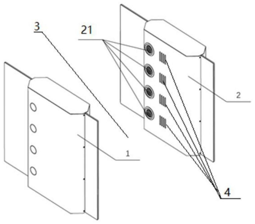
[0023] The blowing module includes an air outlet 11 and a fan, and the air suction module includes an air inlet 21 and a hazardous chemical detector.
[0024] When a passer-by passes through the security inspection channel 3, the air outlet 11 blows air into the security inspection channel 3, and the gas blown from the air outlet 11 blows over the person's human body and luggage surface, and the dangerous chemicals contaminated on the human body and luggage surface are blown by the gas. Blowing, the gas that blows over the surface of the human body and luggage is sucked...
Embodiment 2
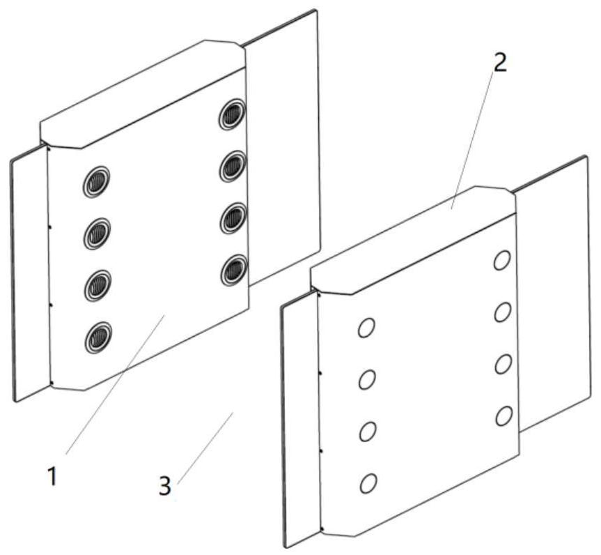
[0039] The above-mentioned embodiment 1 shows the situation that only one blowing module and one suction module are respectively arranged on the first body 1 and the second body 2 . Specifically, the first body 1 and the second body 2 have only one row of air outlets and air suction ports respectively.
[0040] However, multiple air blowing modules and air suction modules (multiple rows of air blowing ports and air suction ports) may also be arranged on the first body 1 and the second body 2 .
[0041] image 3 with Figure 4 An example is shown in which two air blowing modules and two air suction modules are respectively arranged on the first body 1 and the second body 2 and are arranged in the front-back direction of the security inspection channel. That is, if image 3 with Figure 4 As shown, on the first body 1 and the second body 2, there are two rows of air outlets 11 and air suction ports 21 arranged in the front and back direction of the security inspection passag...
PUM
 Abstract
Description
Claims
Application Information