Auxiliary mechanism of direct current contactor

A technology of DC contactors and auxiliary mechanisms, which is applied in the direction of relays, electromagnetic relays, detailed information of electromagnetic relays, etc., and can solve problems affecting the performance of contactors, etc.

Pending Publication Date: 2020-10-23
昆山国力源通新能源科技有限公司
View PDF0 Cites 1 Cited by
  • Summary
  • Abstract
  • Description
  • Claims
  • Application Information

AI Technical Summary

Problems solved by technology

However, this way of designing direct contact between the two auxiliary contact pieces has the ris

Method used


Image

  • Auxiliary mechanism of direct current contactor
  • Auxiliary mechanism of direct current contactor
  • Auxiliary mechanism of direct current contactor

Examples


Embodiment 1

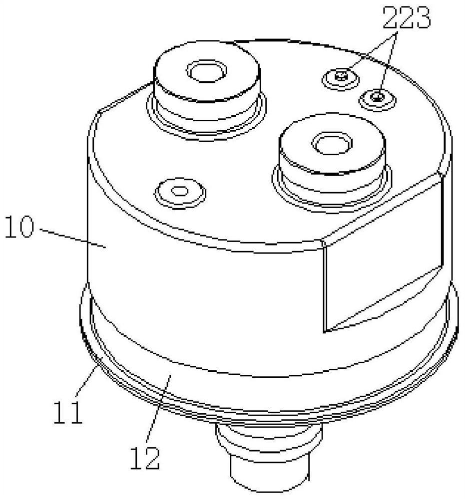
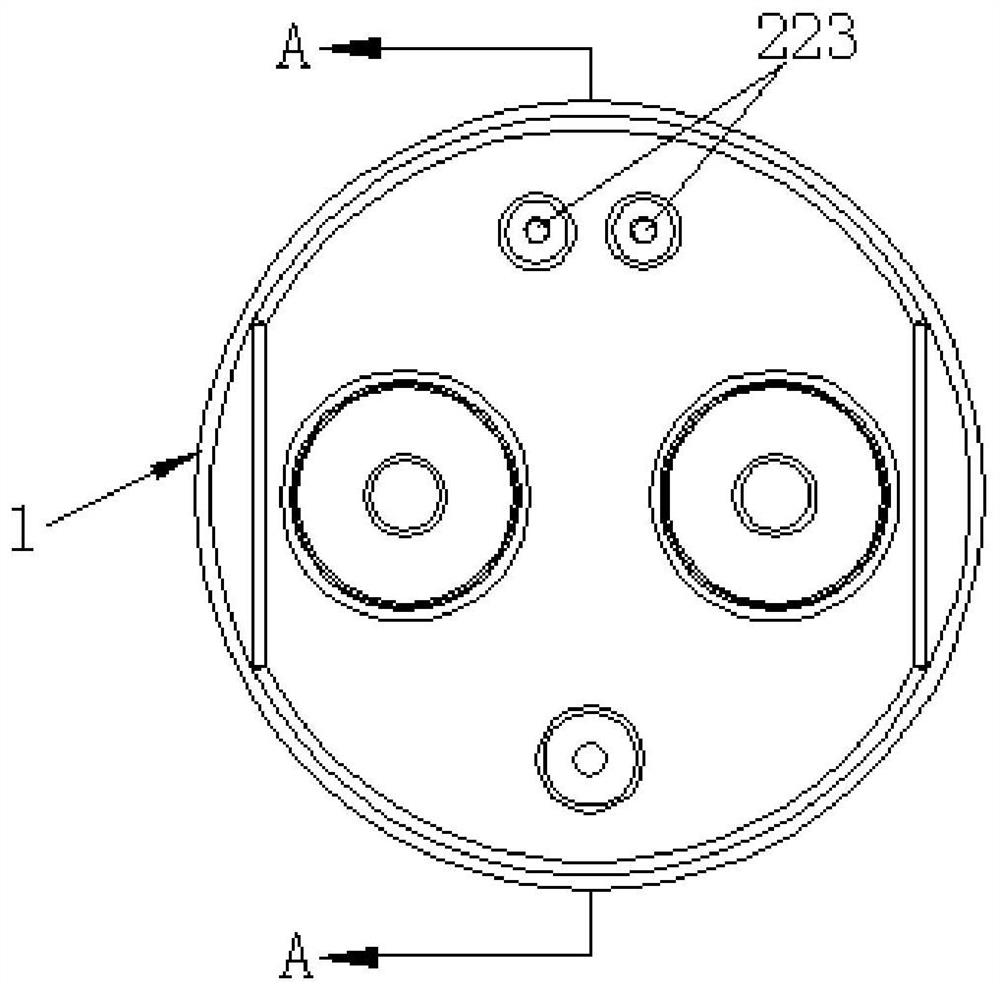
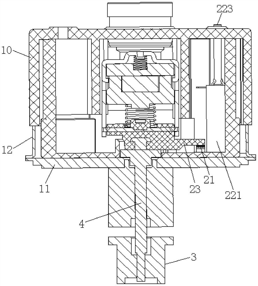
[0032] Please refer to the attached figure 1 to attach Figure 4 As shown, they are respectively a partial three-dimensional structure schematic diagram, a top view structural schematic diagram, an A-A cross-sectional structural schematic diagram and a disassembled structural schematic diagram of the DC contactor installed with the auxiliary mechanism of the present invention.

[0033] The present invention provides an auxiliary mechanism for a DC contactor. The DC contactor includes an arc extinguishing chamber 1 and a driving coil arranged outside the arc extinguishing chamber 1. The auxiliary mechanism includes a shielding ring 20, a trigger conductor 21 and a detection assembly. The shielding ring 20 is built in the arc extinguishing chamber 1, the trigger conductor 21 and the detection assembly are respectively built in the space surrounded by the shielding ring 20, and when the driving coil is in a de-energized state or In the energized state, the trigger conductor 21 c...


PUM


Abstract

The invention discloses an auxiliary mechanism of a direct-current contactor. The direct current contactor comprises an arc extinguishing cavity and a driving coil arranged outside the arc extinguishing cavity; the auxiliary mechanism comprises a shielding ring, a trigger conductor and a detection assembly. The shielding ring is arranged in the arc extinguishing cavity; the trigger conductor and the detection assembly are arranged in a space defined by the shielding ring, and when the driving coil is in a non-powered-on state or a powered-on state, the trigger conductor can correspondingly make contact with or disconnect from the connecting elastic piece on the detection assembly, and then the detection assembly is correspondingly in a powered-on state or a powered-off state. The auxiliarymechanism of the DC contactor is simple, novel and reasonable in structure, and can greatly improve the working accuracy, stability and reliability of the DC contactor.

Description

technical field [0001] The invention relates to the technical field of DC contactors, and specifically provides a DC contactor auxiliary mechanism. Background technique [0002] In order to determine the working state of the DC contactor, it is necessary to determine whether the auxiliary contact is on or off, so as to improve the safety of the product in actual use. [0003] However, due to the sealed design of the DC contactor, the DC contactors currently on the market generally do not have auxiliary contacts. Even if they have auxiliary contacts, most of them are in the form of micro switches or auxiliary contacts. Among them, 1) The micro switch is used to determine whether the contactor is conducting, mainly by driving the transmission push rod, and installing a plastic sheet on the transmission push rod, and the micro switch is moved while the plastic sheet moves up and down with the transmission rod. On and off, and then realize the judgment of the working state of t...

Claims


Application Information

Patent Timeline
IPC IPC(8): H01H50/08H01H50/00
CPCH01H50/00H01H50/08
Inventor 邱广庭杨鑫烨文艳慧顾春朋
Owner 昆山国力源通新能源科技有限公司
Why Eureka
Try Eureka