
C-shaped steel punching device for steel structure production

A punching device, C-shaped steel technology, applied in the field of C-shaped steel punching, can solve problems such as low punching efficiency, noise, and unstable pushing process, so as to improve effectiveness, ensure accuracy, and overcome instability problem effect

Inactive Publication Date: 2020-10-27
六安市汇鑫钢结构有限公司
View PDF1 Cites 1 Cited by
  • Summary
  • Abstract
  • Description
  • Claims
  • Application Information

AI Technical Summary

Problems solved by technology

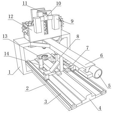
[0003] After searching, the Chinese patent application number is CN201820406671.1, which discloses a C-shaped steel forming punching mechanism, which belongs to the technical field of steel manufacturing, and has the technical problem of low punching efficiency. The main point of the technical solution is a C-shaped steel forming The punching mechanism includes a frame on which a flattening assembly and a forming roller set are sequentially rotated and connected. The flattening assembly includes an upper pressing roller and a lower pressing roller which are arranged oppositely, and the forming roller set includes an upper forming roller and a forming roller which are arranged oppositely. lower roll
A C-shaped steel forming punching mechanism in the above patent has the following disadvantages: the punching method adopted by the overall device is a punching cylinder, which will not only cause a certain impact on the C-shaped steel, making it unstable during the pushing process, And can produce noise in punching process, therefore, need badly a kind of punching device based on steel structure production C-shaped steel

Method used


Image

  • C-shaped steel punching device for steel structure production
  • C-shaped steel punching device for steel structure production
  • C-shaped steel punching device for steel structure production

Examples


Embodiment Construction

[0027] The technical solution of this patent will be further described in detail below in conjunction with specific embodiments.

[0028] Embodiments of the present patent are described in detail below, examples of which are shown in the drawings, wherein the same or similar reference numerals designate the same or similar elements or elements having the same or similar functions throughout. The embodiments described below by referring to the figures are exemplary and are only used for explaining the patent, and should not be construed as limiting the patent.

[0029] In the description of this patent, it is to be understood that the terms "center", "upper", "lower", "front", "rear", "left", "right", "vertical", "horizontal", The orientation or positional relationship indicated by "top", "bottom", "inner", "outer", etc. is based on the orientation or positional relationship shown in the drawings, and is only for the convenience of describing this patent and simplifying the des...


PUM


Abstract

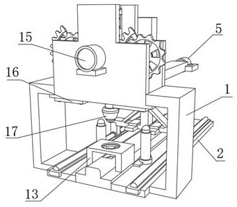
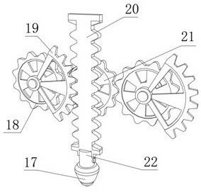
The invention discloses a C-shaped steel punching device for steel structure production, and relates to the technical field of the punching technology of C-shaped steel. In order to solve the problemof the stability of punching, the device includes two fixing frames, two stop plates are arranged on the outer walls of the opposite sides of the fixing frames, a gear punching mechanism is arranged on the outer walls of the opposite sides of the stop plates, a punching head is arranged on the outer wall of the bottom end of the gear punching mechanism, and a heating mechanism is arranged in the punching head. Fixing base plates are arranged on the outer walls of the two sides of the bottoms of the stop plates respectively, connecting plates are arranged on the outer walls of the opposite sides of the bottoms of the fixing frames respectively, a same guide rail is arranged on the outer walls of the opposite sides of the connecting plates separately, an U-shaped frame is arranged on the outer wall of one side of the top of the guide rail, a guide hole is formed in the outer wall of the top of the U-shaped frame, a limit groove is formed in the outer wall, close to the guide hole, of thetop over a sling rail, and a bearing hole is formed in the inner wall of the bottom of the limit groove. The device effectively facilitates the propelling of the C-shaped steel, and guarantees the efficiency of a C-shaped steel punching hole.

Description

technical field [0001] The invention relates to the technical field of punching C-shaped steel, in particular to a punching device based on C-shaped steel for steel structure production. Background technique [0002] The C-shaped steel is automatically processed and formed by the C-shaped steel forming machine. The C-shaped steel forming machine can automatically complete the forming process of the C-shaped steel according to the given C-shaped steel size. The C-shaped steel purlins are divided into 80mm, 100mm, 120mm, and 140mm according to the height. There are five specifications of 160mm and 160mm. The length can be determined according to the engineering design, but considering the conditions of transportation and installation, the total length generally does not exceed 12 meters. [0003] After searching, the Chinese patent application number is CN201820406671.1, which discloses a C-shaped steel forming punching mechanism, which belongs to the technical field of steel ...

Claims


Application Information

Patent Timeline
Patent Type & Authority Applications(China)
IPC IPC(8): B21D28/34B21D28/24B21D28/04B21D37/16
CPCB21D28/002B21D28/04B21D28/243B21D28/34B21D37/16
Inventor 陈露陈培清
Owner 六安市汇鑫钢结构有限公司
Learn More