

Detachable automobile windscreen wiper and disassembling method
A wiper, detachable technology, applied in the automotive field, can solve the problems of friction sound, aging, wiper blade falling off, etc.
- Summary
- Abstract
- Description
- Claims
- Application Information
AI Technical Summary
Problems solved by technology
Method used
Image

Examples
Embodiment 1
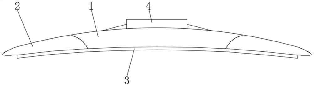
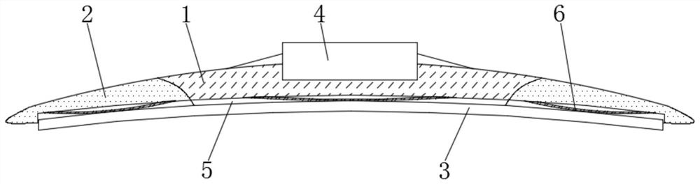
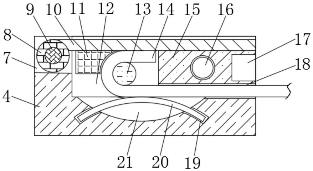
[0029] see Figure 1-4 , the present invention provides a technical solution: a detachable car wiper, including a fixed frame 1, the fixed frame 1 is fixedly connected with a wiper blade 3 for wiping, and the top of the fixed frame 1 is embedded with a fixed The connection block 4, the top of the fixed connection block 4 is provided with a restriction groove 12, the bottom of the restriction groove 12 is provided with a disengagement groove 21, and the inner cavity of the disengagement groove 21 is provided with a limit elastic member 20, and the fixed connection A fixed column 13 is also fixed inside the block 4, and the wiper blade also includes a mounting connection head 14 fixedly connected with the wiper actuating rod, and the mounting connection head 14 has a smooth connection portion and a bending portion, and the bending portion is connected to the The fixing column 13 cooperates to prevent the installation connector 14 from sliding to the right; the distance between t...
PUM
 Abstract
Description
Claims
Application Information