
Novel fixing structure for steel wire rope sleeves and clamping strip

A technology for fixing structures and steel wire ropes, applied in the direction of belts/chains/gears, transmission elements or pulleys, ropes or cables, textile cables, etc., which can solve problems such as complex structures and waste of economic costs

Pending Publication Date: 2020-10-27
深圳中润光电技术股份有限公司
View PDF0 Cites 0 Cited by
  • Summary
  • Abstract
  • Description
  • Claims
  • Application Information

AI Technical Summary

Problems solved by technology

[0002] In the prior art, the method is generally fixed by a wire rope sleeve and a clamping strip, and all the stress points are concentrated on the wire rope sleeve. economic cost, complicating the structure

Method used


Image

  • Novel fixing structure for steel wire rope sleeves and clamping strip
  • Novel fixing structure for steel wire rope sleeves and clamping strip
  • Novel fixing structure for steel wire rope sleeves and clamping strip

Examples


Embodiment Construction

[0016] All features disclosed in this specification, or steps in all methods or processes disclosed, may be combined in any manner, except for mutually exclusive features and / or steps.

[0017] Any feature disclosed in this specification (including any appended claims, abstract and drawings), unless expressly stated otherwise, may be replaced by alternative features which are equivalent or serve a similar purpose. That is, unless expressly stated otherwise, each feature is one example only of a series of equivalent or similar features.

[0018] In describing the present invention, it is to be understood that the terms "one end", "the other end", "outer side", "upper", "inner side", "horizontal", "coaxial", "central", "end ", "length", "outer end" and other indicated orientations or positional relationships are based on the orientations or positional relationships shown in the drawings, which are only for the convenience of describing the present invention and simplifying the d...


PUM


Abstract

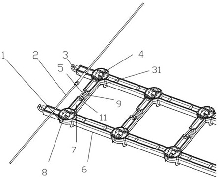
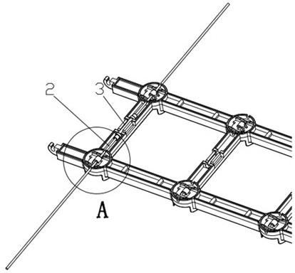
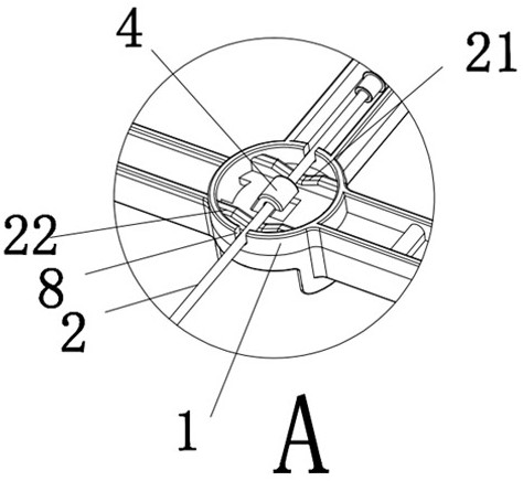
The invention discloses a novel fixing structure for steel wire rope sleeves and a clamping strip. The fixing structure comprises the fixing clamping strip. A plurality of positioning parts are symmetrically disposed on the fixing clamping strip. Every two adjacent positioning parts are connected with each other through an assembling strip. A clamping strip sleeve buckle is disposed in the middleof each assembling strip. A sleeve slot is formed in each clamping strip sleeve buckle. The two sides of each steel wire rope are positioned and assembled on the two corresponding positioning parts. The steel wire rope sleeve is disposed in the middle of each steel wire rope. The bottom of each steel wire rope sleeve is disposed in the sleeve slot of the corresponding clamping strip sleeve buckleto be positioned. Each steel wire rope extends out of the two side faces of the corresponding positioning parts. By means of the novel fixing structure, the number of the steel wire rope sleeves usedis reduced by half compared with an original traditional method, so that cost is saved, the fixing firmness effect of the steel wire ropes and the clamping strip is just the same, and the flexibilityof the steel wire ropes is sufficiently utilized to realize the effect of assembling in place; and when the clamping strip is hung, the steel wire ropes share two thirds of fastening stress, and the direct stress between the steel wire rope sleeves and the clamping strip is greatly relieved.

Description

technical field [0001] The invention relates to the field of LED display screens, in particular to a novel fixing structure for a steel wire rope sleeve and clamping strips. Background technique [0002] In the prior art, the method is generally fixed by a wire rope sleeve and a clamping strip, and the stress points are all concentrated on the wire rope sleeve. The economic cost complicates the structure. Contents of the invention [0003] The technical problem to be solved by the present invention is a new type of fixing structure for steel wire rope sleeves and clamps. The number of steel wire rope sleeves used is reduced by half compared with the original traditional method, which saves costs and has the same effect on the fixing firmness of steel wire ropes and clamps. [0004] The present invention is achieved through the following technical proposals: a new type of fixing structure between the steel wire rope casing and the clip bar, including a fixed clip bar, and ...

Claims


Application Information

Patent Timeline
IPC IPC(8): F16G11/02
CPCF16G11/02
Inventor 魏文红
Owner 深圳中润光电技术股份有限公司
Learn More