Adjustable electronic device display bracket

A technology for electronic equipment and display brackets, which is applied to mechanical equipment, machine/stands, supporting machines, etc., and can solve the problem that the adjustment flexibility cannot meet the actual needs of use.

Inactive Publication Date: 2020-10-27
NANJING COLLEGE OF INFORMATION TECH
View PDF9 Cites 4 Cited by
  • Summary
  • Abstract
  • Description
  • Claims
  • Application Information

AI Technical Summary

Problems solved by technology

[0003] The patent application publication No. CN109155116 A discloses a display stand, which has a support portion supporting the display, a base in contact with the placement surface, and a pillar connecting the support portion and the base, and the pillar has a plurality of pillars components, the plurality of strut members are arranged to overlap each other and can slide each other, the support portion is disposed on the first strut member as one of the plurality o

Method used


Image

  • Adjustable electronic device display bracket
  • Adjustable electronic device display bracket
  • Adjustable electronic device display bracket

Examples


Embodiment 1

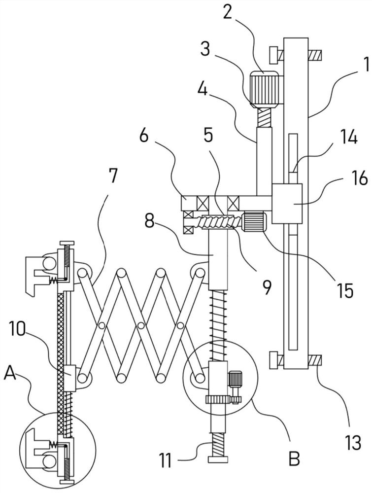
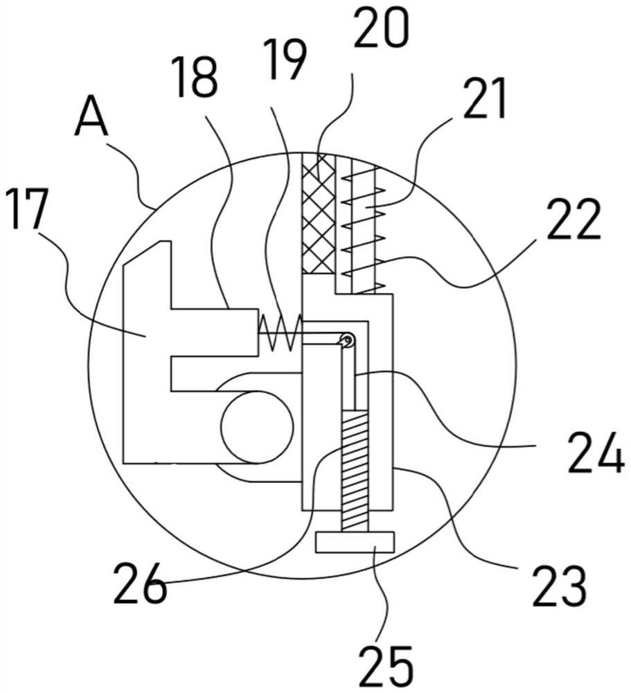
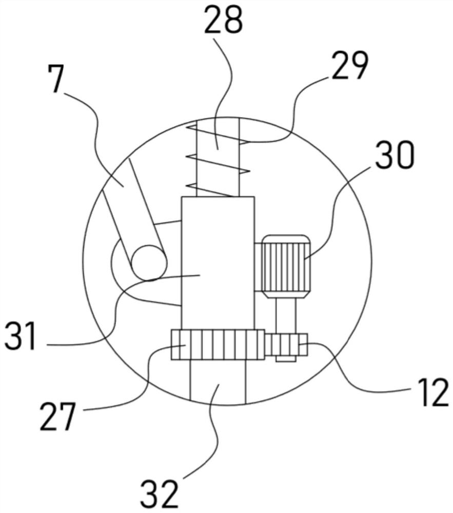
[0026] see Figure 1 to Figure 4 , an adjustable electronic device display bracket, comprising a fixed plate 1, an expansion bolt 13 is installed on the fixed plate 1, a lifting motor 2 is fixed on the fixed plate 1, and a support plate 6 is installed on the lifting motor 2 through a lifting adjustment mechanism , the bottom of the support plate 6 is rotated with a steering column 8, and the front and rear telescopic mechanisms are installed on the steering column 8. The front and rear telescopic mechanisms are equipped with a mounting plate 23, and the mounting plate 23 is provided with a pair of mounting plates for fixing the display. As for the clamping mechanism, the support plate 6 is provided with a steering mechanism for driving the steering column 8 .

[0027] The device fixes the fixing plate 1 on the wall through the expansion bolts 13 provided, and the display can be fixed on the mounting plate 23 through a pair of clamping mechanisms provided to ensure the stable i...

Embodiment 2

[0034] On the basis of Embodiment 1, in addition, the device is also provided with a lifting adjustment mechanism, including a threaded sleeve 4 vertically fixed on the support plate 6, and the threaded sleeve 4 is threadedly connected with the output shaft of the lifting motor 2 Coaxially fixed threaded shaft 3.

[0035] One side of the fixed plate 1 is provided with a chute in the vertical direction, and a guide block 14 is slidably embedded in the chute. The lifting adjustment mechanism also includes a lifting frame 16 fixedly connected with the support plate 6, and the inner wall of the lifting frame 16 is fixed with a guiding block. 14. The lifting frame 16 can slide relative to the fixed plate 1 in the vertical direction through the guide block 14 .

[0036]Through the above settings, the lifting motor 2 can drive the threaded shaft 3 to rotate, the threaded shaft 3 drives the threaded sleeve 4 that is threadedly connected to it to vertically lift, and the threaded sleev...


PUM


Abstract

The invention discloses an adjustable electronic device display bracket, and relates to the technical field of display brackets. The adjustable electronic device display bracket comprises a fixing plate. A front and rear telescopic mechanism is provided with a mounting plate. The mounting plate is provided with a pair of clamping mechanisms for fixing a monitor. A support plate is provided with asteering mechanism for driving a steering column. By arranging the clamping mechanisms, the monitor can be stably clamped and fixed on the mounting plate. The installation and disassembly of the monitor is simple and convenient. By arranging the front and rear telescopic mechanism, the translation effect of the mounting plate can be realized with the help of the extension of a scissor brace, and the distance between viewers and the monitor can be adjusted flexibly. By arranging a lifting adjusting mechanism, the height of the monitor on the mounting plate can be adjusted vertically to be convenient for users to watch and use more comfortably. By arranging the steering mechanism, the display angle of the monitor can be adjusted circumferentially, thus greatly improving the flexibility of anexternal monitor of electronic equipment.

Description

technical field [0001] The invention relates to the technical field of display brackets, in particular to an adjustable display bracket for electronic equipment. Background technique [0002] Displays are also often referred to as monitors. The display is an I / O device belonging to the computer, that is, an input and output device. It is a display tool that displays a certain electronic file on the screen through a specific transmission device and then reflects it to the human eye. It can be divided into CRT, LCD and other types. Currently, the display of an electronic device needs to use a support frame to support and limit the position, so as to ensure the normal use of the display. [0003] The patent application publication No. CN109155116 A discloses a display stand, which has a support portion supporting the display, a base in contact with the placement surface, and a pillar connecting the support portion and the base, and the pillar has a plurality of pillars comp...

Claims


Application Information

Patent Timeline
IPC IPC(8): F16M11/18F16M11/08F16M11/04F16M13/02
CPCF16M11/04F16M11/08F16M11/18F16M13/02
Inventor 袁小燕顾振飞鲍安平王书旺张志友文爱鑫
Owner NANJING COLLEGE OF INFORMATION TECH
Why Eureka
Try Eureka