Excavator bucket tooth

A technology of excavator bucket teeth and bucket teeth, which is applied in the field of machinery, can solve problems such as hindering the installation of new bucket teeth, cumbersome installation operations, and difficult removal, and achieve the effects of simple and convenient installation and disassembly, improved utilization rate, and good stability

Active Publication Date: 2013-08-14
宁波市鄞州精铸五金厂
View PDF7 Cites 10 Cited by
  • Summary
  • Abstract
  • Description
  • Claims
  • Application Information

AI Technical Summary

Problems solved by technology

[0004] Although the above-mentioned excavator bucket teeth have the advantages of simple structure, long service life and wide application range, they still have the following disadvantages: 1. Since the pin and the pin hole are tightly connected, the pin needs to be knocked hard during installation. 2. After using for a long time to cause the pin to break, the broken pin still stays in the pin hole, blocking the pin hole, which is not easy to remove, and hinders the installation of new bucket teeth. installation, uneconomical

Method used


Image

  • Excavator bucket tooth
  • Excavator bucket tooth
  • Excavator bucket tooth

Examples


Embodiment 1

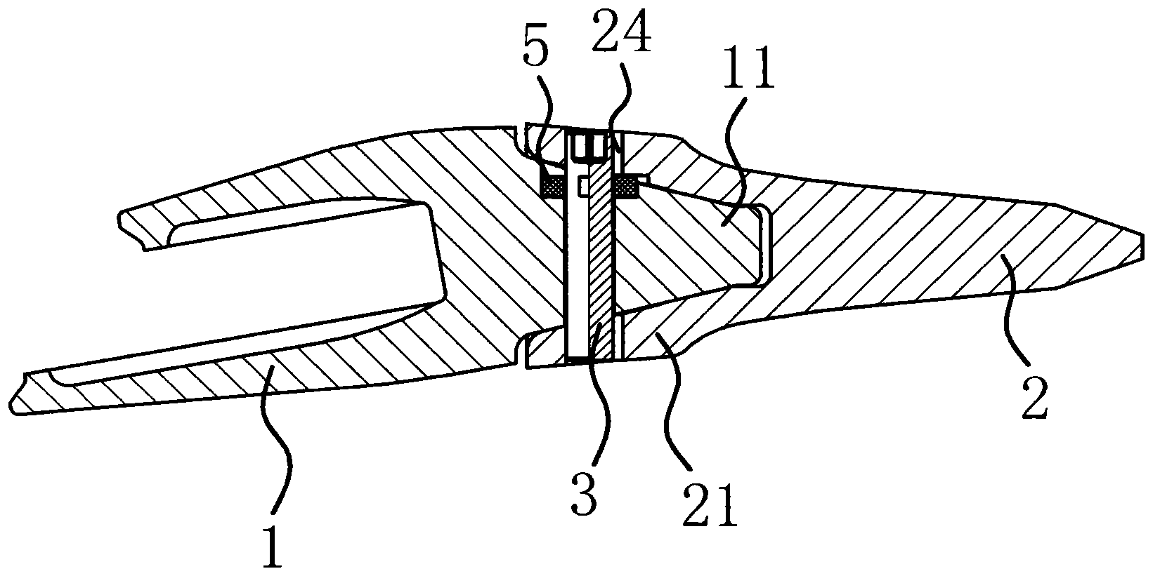
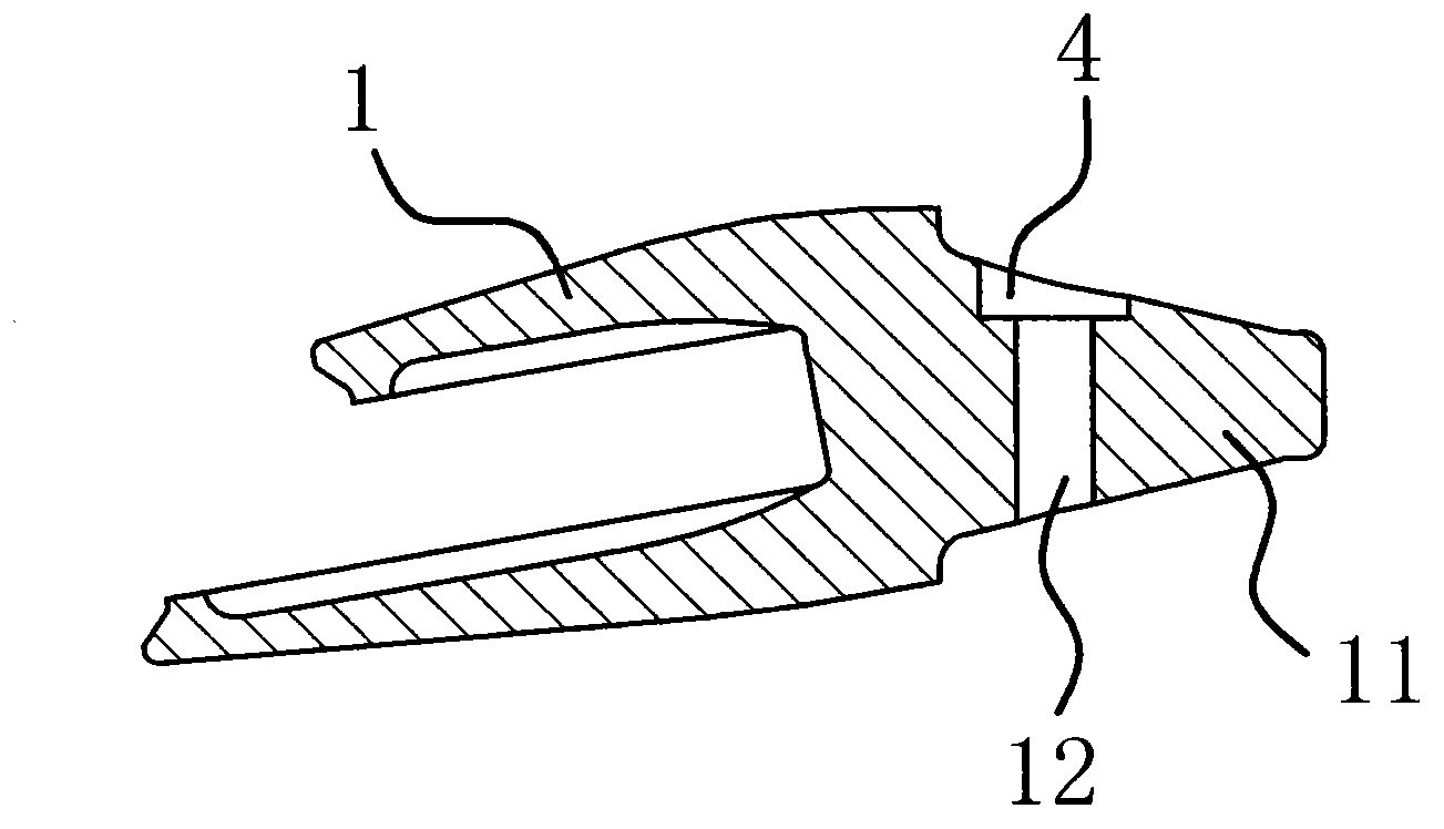
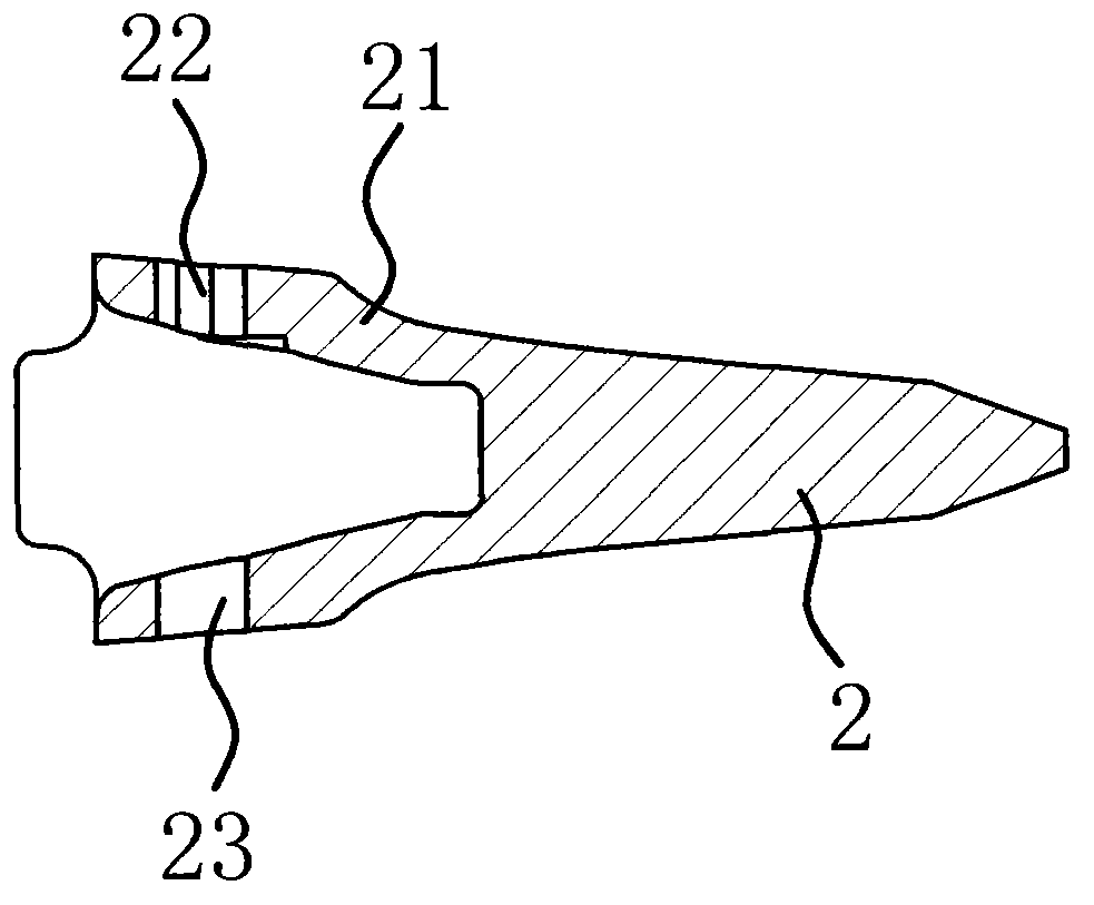
[0036] Such as figure 1 As shown, the bucket tooth 2 of the excavator includes a tooth holder 1 with a mounting portion 11 and a bucket tooth 2 with a connecting portion 21 , and the mounting portion 11 is inserted into the connecting portion 21 . Such as figure 2 As shown, the mounting part 11 has a mounting hole 12 arranged through it, as image 3 As shown, the connecting portion 21 has a second installation hole 22 and a third installation hole 23 arranged through it, and the second installation hole 22 and the third installation hole 23 are arranged coaxially. In this embodiment, the second mounting hole 22, the first mounting hole 12 and the third mounting hole 23 form a through pin hole, such as figure 1 As shown, a pin 3 is pierced in the pin hole. Specifically, such as Figure 4 and Figure 5 As shown, the outer wall of the pin 3 has a radially protruding positioning portion 31, such as figure 1 As shown, the inner side wall of the second mounting hole 22 has a ...

Embodiment 2

[0047] The principle of this embodiment is basically the same as that of Embodiment 1, the difference is that, as Figure 7 and Figure 8 As shown, the first mounting hole 12 is horizontally penetrated on the mounting part 11, such as Figure 9 As shown, the second mounting hole 22 and the third mounting hole 23 are horizontally penetrated on the connecting part 21, and as Figure 9 As shown, the positioning groove 4 is provided on the connecting portion 21 .


PUM


Abstract

The invention provides an excavator bucket tooth and belongs to the technical field of machinery. The problem that existing excavator bucket teeth are inconvenient to install and dismantle and unfirm in structure is solved. The excavator bucket tooth comprises a tooth seat provided with an installing portion and a bucket tooth body provided with a connecting portion, wherein the installing portion is inserted into the connecting portion, a first installing hole which is through is arranged at the installing portion, and a second installing hole and a third installing hole which are through are arranged at the connecting portion. The second installing hole and the third installing hole are coaxial, the first installing hole, the second installing hole and the third installing hole form a through pin hole, a pin penetrates into the pin hole, an outer side wall of the pin is provided with a radially protruding positioning portion, an inner side wall of the second installing hole is provided with a guide groove matched with the positioning portion, the inner end of the guide groove is communicated with a positioning groove arranged between the installing portion and the connecting portion, and the axial length of the positioning groove is slightly larger than that of the positioning portion. The excavator bucket tooth has the advantages of being convenient to install and dismantle, firm in structure, high in stability and the like.

Description

technical field [0001] The invention belongs to the technical field of machinery, and relates to an excavator component, in particular to an excavator bucket tooth. Background technique [0002] An excavator is an earth-moving machine that uses a bucket to excavate materials higher or lower than the bearing surface, and loads them into transport vehicles or unloads them to the stockyard. Excavators have become one of the most important construction machinery in engineering construction. Construction sites such as reconstruction and high-speed rail construction are widely used. The edge of the excavator bucket is equipped with bucket teeth and tooth holders, which need to be fixed with pins, which means that the tooth holders and bucket teeth must have pin holes that match the pins, and the tooth holders Welded on the bucket edge of the excavator. Due to the various powerful forces impacting the bucket teeth and the tooth seat during the construction of the excavator, the p...

Claims


Application Information

Patent Timeline
Patent Type & Authority Applications(China)
IPC IPC(8): E02F9/28
Inventor 张灵
Owner 宁波市鄞州精铸五金厂
Why Eureka
Try Eureka