Sensor magnet holder, motor having the holder incorporated therein, and method of manufacturing the motor

一种传感器、保持器的技术,应用在制造电动发电机、电动组件、机电装置等方向,能够解决蜗轮的润滑脂流到霍尔传感器的基板侧、传感器磁体停止的转矩不足等问题,达到不易裂纹、提高耐移动能力的效果

Active Publication Date: 2010-01-20
MABUCHI MOTOR
View PDF3 Cites 28 Cited by
  • Summary
  • Abstract
  • Description
  • Claims
  • Application Information

AI Technical Summary

Problems solved by technology

[0006] As described above, for the positioning and fixing of the sensor magnet with respect to the magnet holder and the positioning and fixing of the magnet holder with respect to the shaft, the rotation detecting device shown in the figure has various complicated shapes, and it is necessary to make the sensor magnet rotate in the circumferential direction. Insufficient torque for stopping
[0007] In addition, the rotation detection device shown in the figure assumes that it is arranged adjacent to the converter, but if it is arranged adjacent to the worm wheel, there is a possibility that the grease of the worm wheel may flow to the board side of the Hall sensor.

Method used


Image

  • Sensor magnet holder, motor having the holder incorporated therein, and method of manufacturing the motor
  • Sensor magnet holder, motor having the holder incorporated therein, and method of manufacturing the motor
  • Sensor magnet holder, motor having the holder incorporated therein, and method of manufacturing the motor

Examples


Embodiment Construction

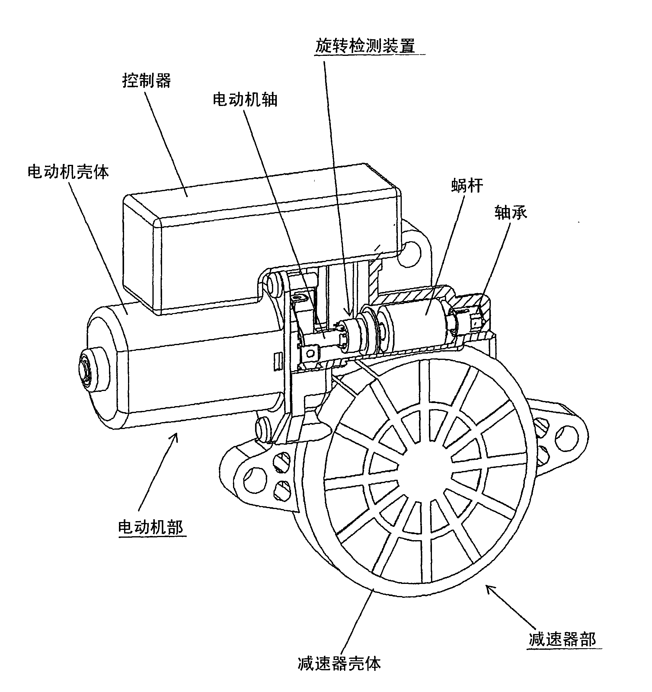
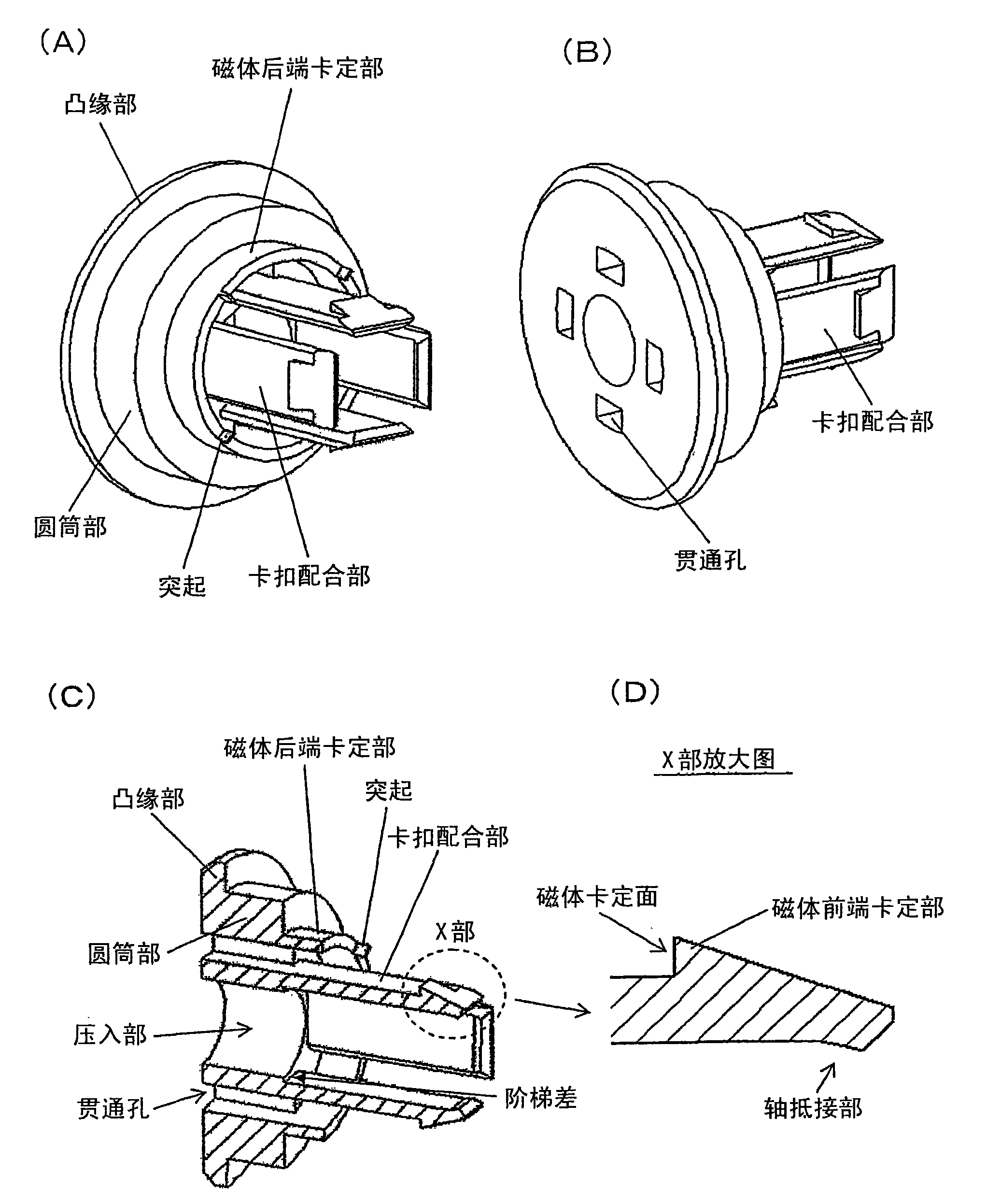
[0031] Hereinafter, the present invention will be described based on examples. The technology of the present invention, which positions and fixes the sensor magnet to a predetermined position on the shaft, can be applied to a brushless motor or a motor equipped with a worm gear reducer that needs to detect the rotation speed and rotation position as described above in the prior art. All small motors, but the following is an example for the case of motors equipped with worm gear reducers.

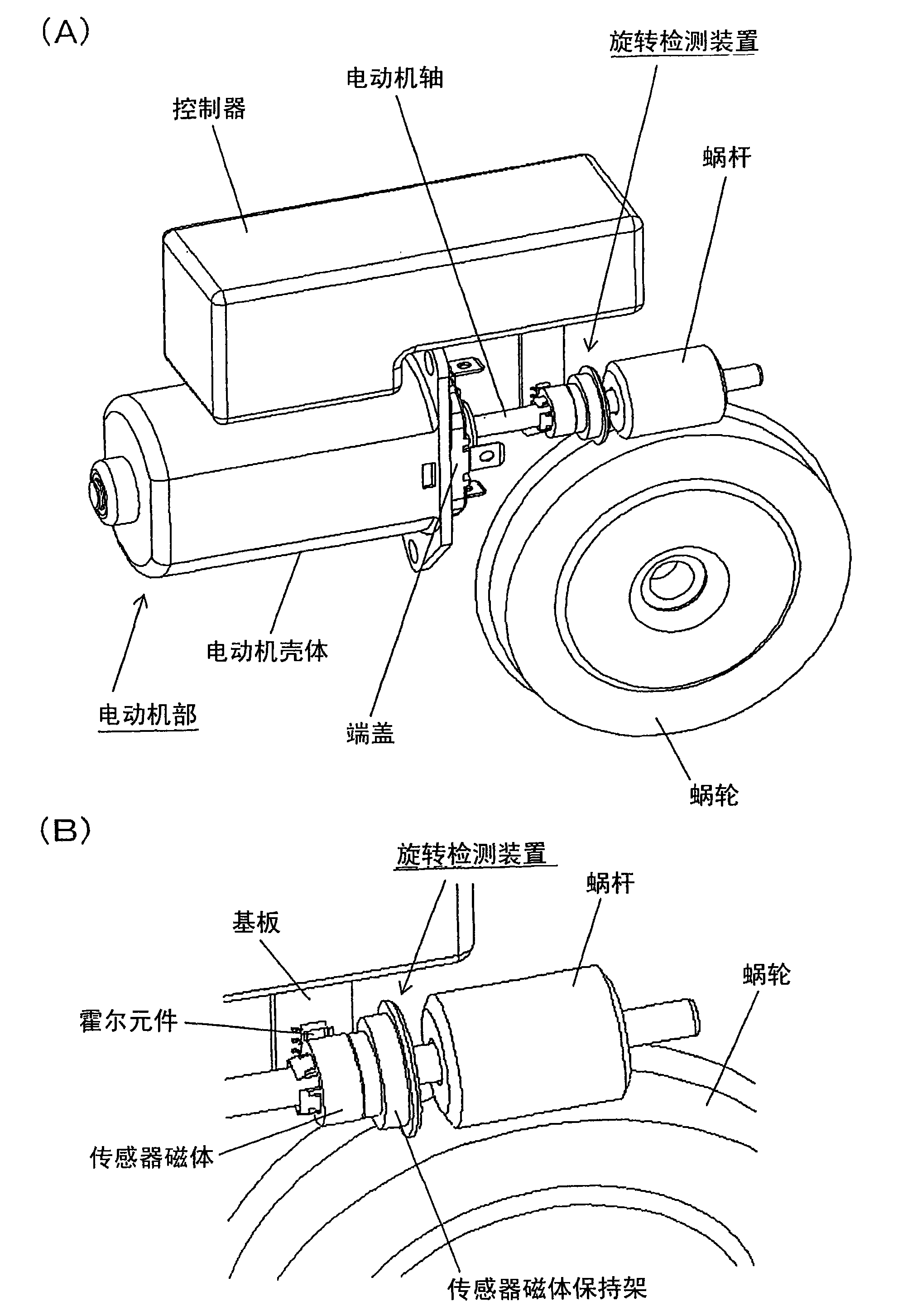
[0032] figure 1 It is a perspective view partially showing the overall structure of the electric motor with the worm gear reducer including the rotation detection device in cross-section. figure 2 (A) is a perspective view showing the rotation detection device in a state where the reduction gear case and the like are removed, and (B) is a perspective view showing a part of the rotation detection device enlarged. The speed reducer section and the controller controlling them are connected ...


PUM


Abstract

A sensor magnet holder is formed such that a cylindrical portion, a flange portion formed by increasing the diameter of one end part of the cylindrical portion, a magnet rear-end engagement portion formed at the other end part of the cylindrical portion, and four plate-like snap fit tongues are formed integral with one another. The cylindrical portion including the flange portion has, on its inner diametral side, a press fit portion to be press-fitted to a motor shaft. The four plate-like snap fit tongues have respective magnet front-end engagement portions formed on an outer diametral side of their tip portions. The four snap fit tongues are brought into contact with respective flat inner surfaces of the sensor magnet having four flat inner surfaces, by utilizing elasticity of the snap fit tongues. The sensor magnet is retained between the magnet rear-end engagement portion and the magnet front-end engagement portions.

Description

technical field [0001] The present invention relates to a mounting holder for a sensor magnet for obtaining a signal corresponding to a change in the rotational position of a rotor by detecting a change in magnetic pole position with rotation of a motor shaft, and a motor assembled with the holder and its manufacture method. Background technique [0002] In a small electric motor, a rotation detection device for detecting its rotational speed and rotational position is integrally integrated with a motor rotating portion such as a motor shaft and used. For example, such a rotation detection device is used in a brushless motor to obtain information on its rotational position. As is well known, a brushless motor is equipped with a magnet called a sensor magnet whose magnetic poles are alternately formed in the circumferential direction on a rotating shaft, and a magnetic induction element is provided in the vicinity thereof. Since the sensor magnet is magnetized corresponding...

Claims


Application Information

Patent Timeline
Patent Type & Authority Applications(China)
IPC IPC(8): H02K29/08H02K15/00
CPCH02K7/1166H02K11/0021H02K23/66H02K11/215Y10T29/49002Y10T29/5313
Inventor 菊地悟志秋本隆宏
Owner MABUCHI MOTOR
Why Eureka
Try Eureka