Camera driver

A driving device and camera technology, applied in the direction of camera focusing device, camera, projector focusing device, etc., can solve the problems of large rotation radius, mechanical looseness, increased friction load, etc.

Active Publication Date: 2010-07-07
PANASONIC INTELLECTUAL PROPERTY CORP OF AMERICA
View PDF6 Cites 27 Cited by
  • Summary
  • Abstract
  • Description
  • Claims
  • Application Information

AI Technical Summary

Problems solved by technology

However, the contact portion of the lens holder and the bracket installed on the outside has a large radius of rotation, so the frictional load applied to the movable part increases, and the movement distance becomes larger.
As a result, it is considered that as the inclination angle becomes larger, the fluctuation of the contact friction load increases, making accurate control difficult
In addition, when the distance between the lens holder and the bracket provided outside it is not correctly controlled, it is difficult to correctly control the inclination angle of the lens holder.
Depending on the processing accuracy of these parts, mechanical looseness may occur, which may hinder the frequency response characteristics of the movable part
[0013] In addition, the devices of Patent Documents 1 to 3 do not have a configuration for rotating constituent elements such as lenses around the optical axis of the photographing unit.

Method used


Image

  • Camera driver
  • Camera driver
  • Camera driver

Examples


no. 1 approach

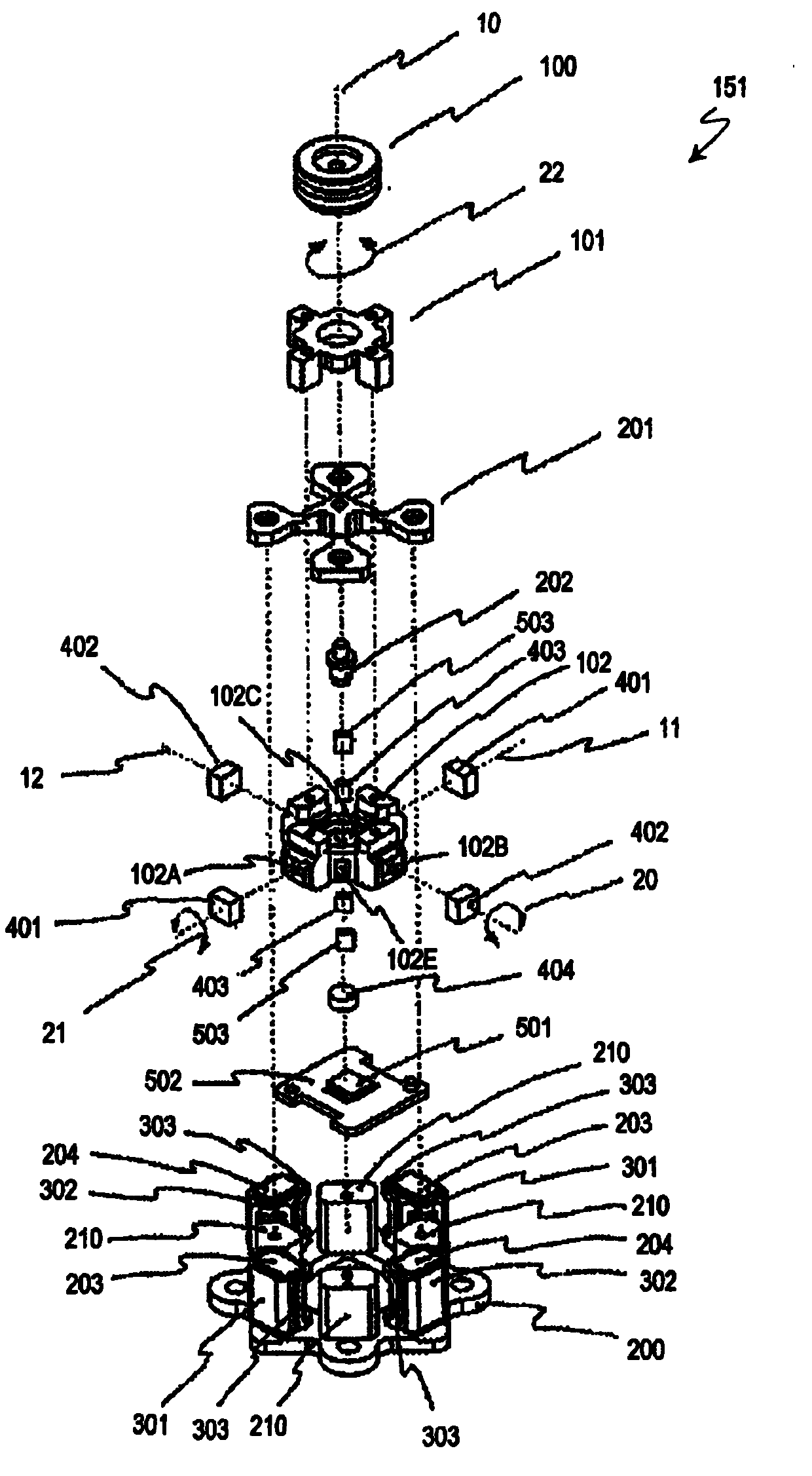
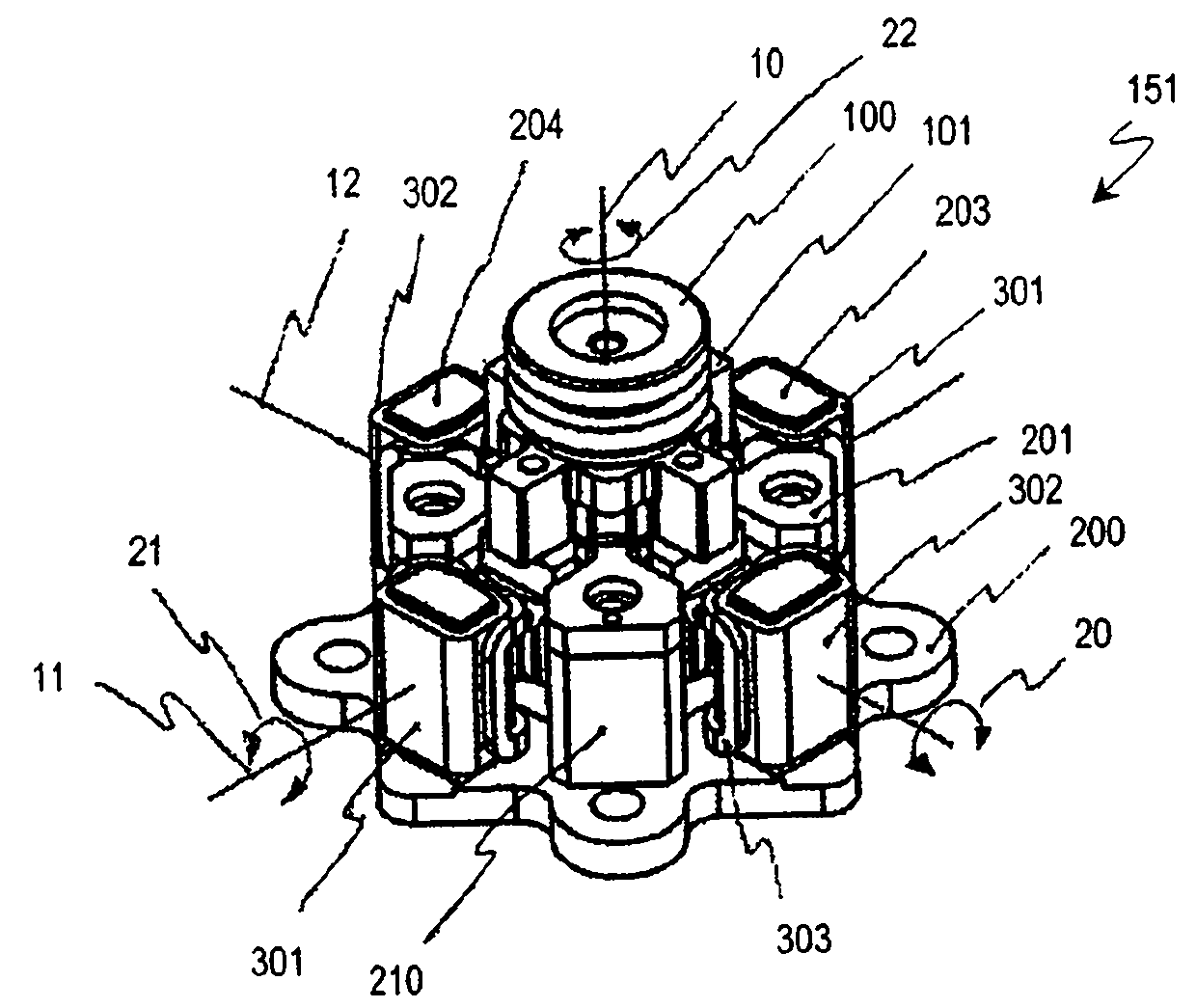
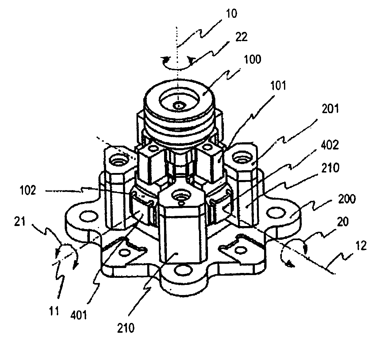
[0174] Next, a first embodiment of the camera driving device of the present invention will be described. figure 1 is an exploded perspective view showing the camera driving device 151 according to the first embodiment of the present invention, figure 2 It is a perspective view of the camera driving device 151 viewed obliquely from above. in addition, image 3 It is a perspective view of the camera driving device 151 in a state in which some components (yaw drive coil 301, pitch drive coil 302, roll drive coil 303, yaw yoke 203, and pitch yoke 204) are removed as viewed obliquely from above. Figure 4 It is a plan view of the camera driving device 151 seen from above. Figure 5 It is a sectional view of the plane including the optical axis 10 and the rotation axis 11 in the pitch direction of the camera driving device 151 . The main configuration of the camera driving device 151 will be described with reference to these figures.

[0175] The camera driving device 151 inclu...

no. 2 approach

[0233] Next, a second embodiment of the camera driving device of the present invention will be described. Figure 10 It is an exploded perspective view showing the configuration of the camera driving device 152 of the second embodiment, Figure 11 It is a plan view of the camera driving device 152 seen from above. In these two figures, the same reference numerals are given to the same constituent elements as those of the first embodiment.

[0234] Such as Figure 10 and Figure 11 As shown, the camera drive device 152 is different from the camera drive device 151 of the first embodiment in that a dedicated drive unit is mounted on the first movable unit 102 to rotate and drive the movable unit in the roll direction 22 .

[0235] The camera driving device 152 includes a pair of rolling drive magnets 800 and a pair of rolling yokes 701 in order to rotate the movable unit in the rolling direction 22 .

[0236] The pair of rolling drive magnets 800 are arranged at 45 degrees w...

no. 3 approach

[0242] Next, a third embodiment of the camera driving device of the present invention will be described. Figure 12 It is an exploded perspective view showing the camera driving device 153 according to the third embodiment of the present invention, Figure 13 It is a perspective view of the camera driving device 153 viewed obliquely from above. in addition, Figure 14 It is viewed from obliquely above with some components removed (yaw drive coil 301, pitch drive coil 302, roll drive coil 303, yaw yoke 203, pitch yoke (coil) 204, and coupling member 210). A perspective view of the camera driving device 153. Figure 15 It is a plan view of the camera driving device 153 seen from above. Figure 16 is the inclusion of the camera driver 153 Figure 15 A sectional view in the plane of line 16 and optical axis 10 is shown. in addition, Figure 17 yes Figure 16 The main schematic cross-sectional view of the cross-sectional view of the camera drive unit 153 is shown. The main ...


PUM


Abstract

The camera driver is provided with a camera part that comprises an image pickup element, a lens that forms an object image on the image pickup surface of the image pickup element and a lens barrel that holds the lens; a fixed unit, at least a portion of which is made of a magnetic substance and which comprises a protruding part provided with a shape that is at least a portion of a spherical surface; a movable unit that comprises a first movable part comprising an attraction magnet that generates a magnetic attraction force on the magnetic substance and a contact surface with a conical shape into which the protruding part fits as a result of the magnetic attraction force, and which rotates freely with respect to the center of the sphere of the spherical surface of the protruding part, and a second movable part, which is equipped with the camera part and fixed to the first movable part, and which comprises a fall-off prevention regulating surface provided with a prescribed intervening gap that allows free rotation with respect to the fixed unit when the first movable part rotates; a detector that detects the slant angle of the camera part with respect to the fixed unit and the rotation angle of the camera part around the optical axis of the lens; a first driving part that slants the camera part with respect to the fixed unit; and a second driving part that rotates the camera part with respect to the fixed unit around the center of the optical axis.

Description

technical field [0001] The present invention relates to a camera driving device capable of tilting a photographing unit including a lens barrel and an imaging element in a yaw direction (yawing) and a pitching direction (pitch) and rotating (rolling) around the optical axis of the photographing unit . Background technique [0002] In recent years, many video cameras and digital cameras on the market are equipped with hand shake correction devices that correct image shake of photographed images caused by hand shake. In this hand-shake correction device, a lens, a lens barrel, a mirror, an imaging element, etc. are tilted with respect to the optical axis of the camera, or moved two-dimensionally in a plane perpendicular to the optical axis. [0003] For example, Patent Document 1 discloses a shake correction mechanism that elastically supports a lens barrel at one point and tilts the lens barrel with respect to the optical axis. Patent Document 2 discloses a hand-shake corre...

Claims


Application Information

Patent Timeline
Patent Type & Authority Applications(China)
IPC IPC(8): G03B5/00
CPCG03B5/00G03B3/10G03B30/00G02B27/646H04N23/6812H04N23/687
Inventor 泷泽辉之江泽弘造稻田真宽杉谷芳明三崎正之
Owner PANASONIC INTELLECTUAL PROPERTY CORP OF AMERICA
Why Eureka
Try Eureka