Drawing device

a drawing device and drawing technology, applied in metal-working hand tools, metal-working apparatuses, metal-working apparatuses, etc., can solve the problems of difficult positioning, difficult clamping to the bottom of the object, and object in a narrow space further difficult to be removed, so as to achieve easy clamping

Inactive Publication Date: 2012-11-15
SHINE YEN IND
View PDF13 Cites 10 Cited by
  • Summary
  • Abstract
  • Description
  • Claims
  • Application Information

AI Technical Summary

Benefits of technology

[0008]The main object of the present invention is to provide a drawing device, having a plurality of clipping rods to provide easy clamping at numeral co-planar positions.
[0014]When operating, the bolt is able to drive the axle portion and the first driving portion to rotate, and the first driving portion further drives the second driving elements to rotate. And then, the second driving elements drive the clipping rods to move between a first position and a second position respectively. Also, each clipping rod is able to turn relative to one of the second driving elements freely, so that the hook portion of each clipping rod is able to face outward or inward alternatively.
[0015]Thereby, the clipping rods are able to clamp from numeral co-planar positions, and stability and safety are both improved.

Problems solved by technology

However, all the elements of the previous drawing device are linked together in a pivot manner, so that hooking to the bottom of the object and positioning are difficult.
Also, an object in a narrow space is further difficult to be removed.
Moreover, the two clipping rods 43 are arc-shaped and bent outward, so that the drawing device is hard to enter a narrow space to operate.
Thus, the object is unable to be removed from the fixed end.

Method used


Image

  • Drawing device
  • Drawing device
  • Drawing device

Examples


first embodiment

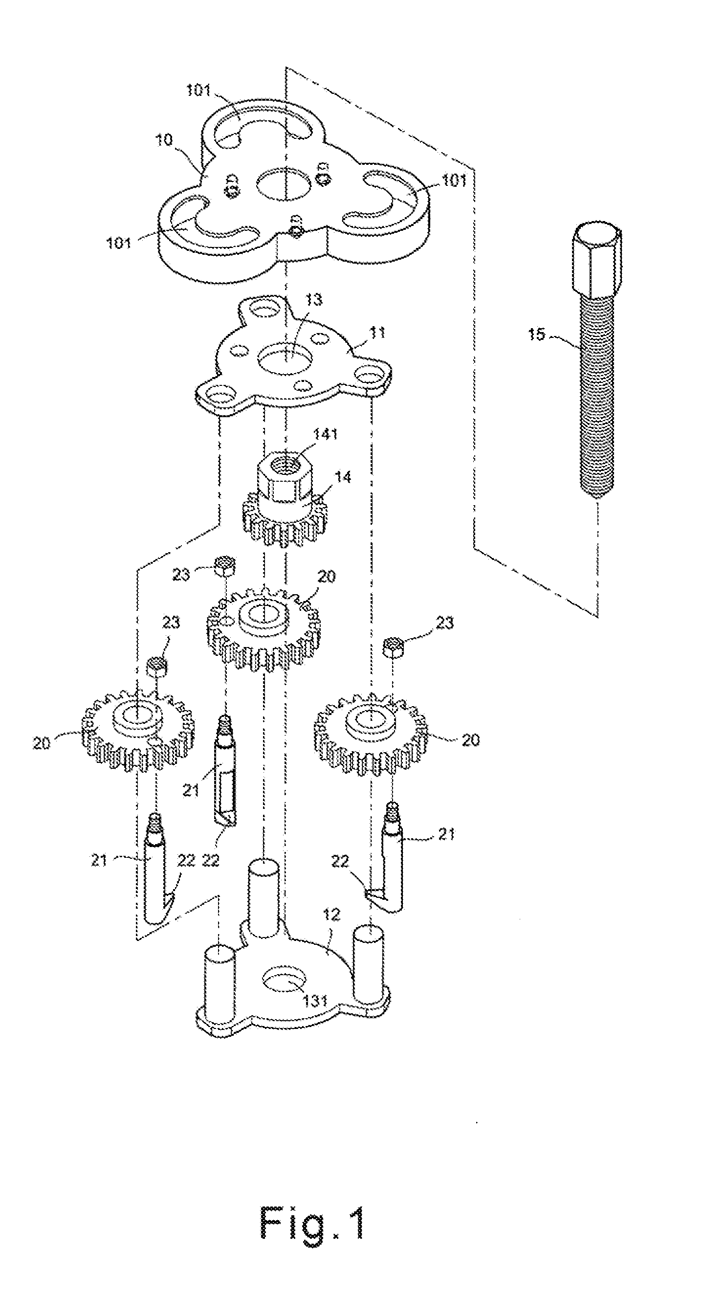
[0026]Please refer to FIG. 1 to FIG. 5 for the present invention. The drawing device of the present embodiment includes a cover 10, an upper shell 11, a lower shell 12, a first driving element 14, a bolt 15, a plurality of second driving elements 20, and a plurality of clipping rods 21.

[0027]The upper and the lower shells are board-shaped and define a receiving room. The cover 10 is disposed on a side of the upper shell 11 away from the lower shell 12. The first driving element 14 and the second driving elements 20 are disposed in the receiving room respectively, and a center of each of the upper or the lower shells 11,12 forms an axle hole 13,131. In the major embodiment, the cover 10 forms a plurality of sliding slots 101. More preferably, the sliding slots extend in an arc shape.

[0028]The first driving element 14 has a first driving portion and an axle portion. An outer peripheral face of the first driving portion forms a plurality of protruding teeth annularly. The axle portion ...

second embodiment

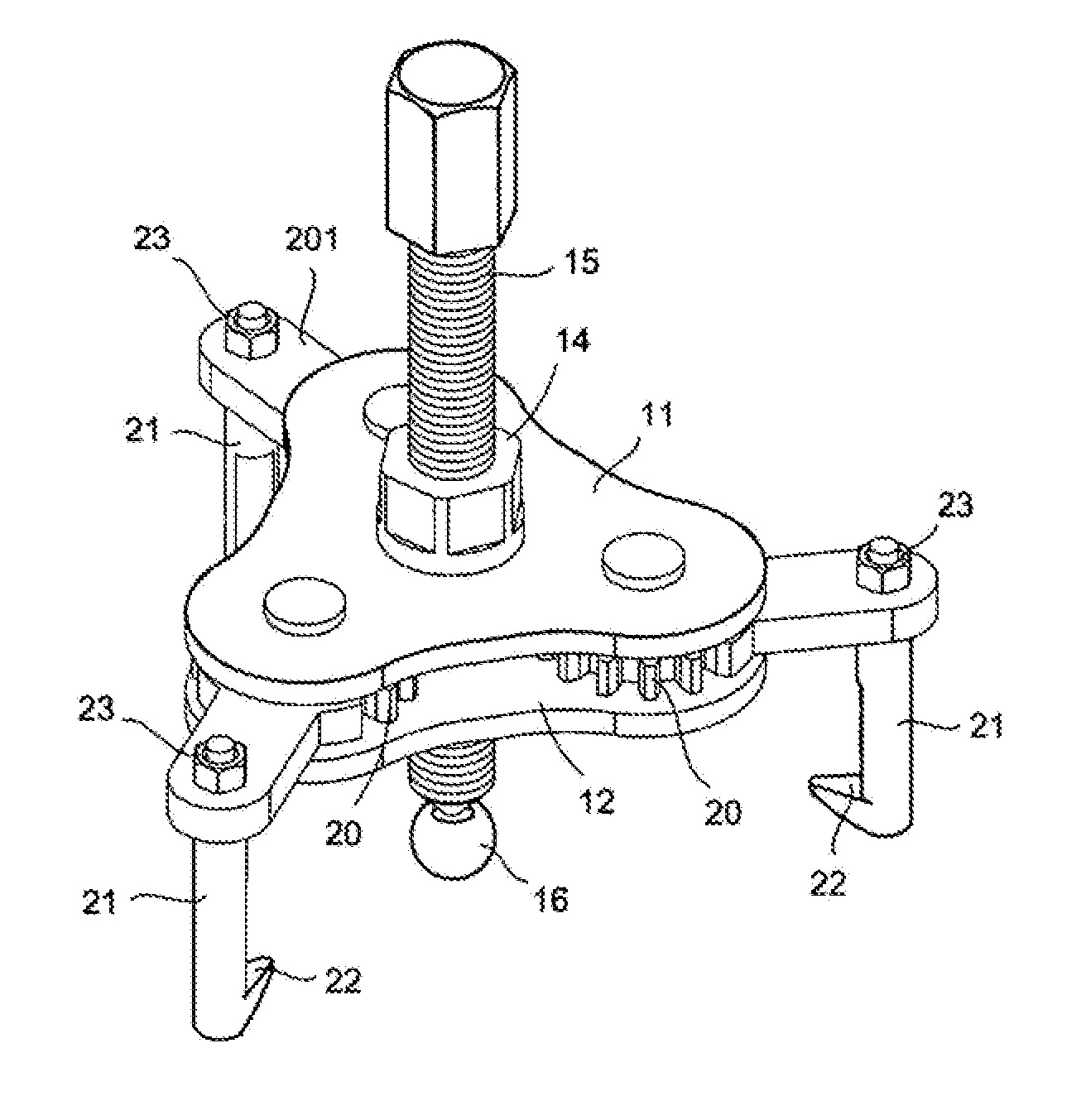
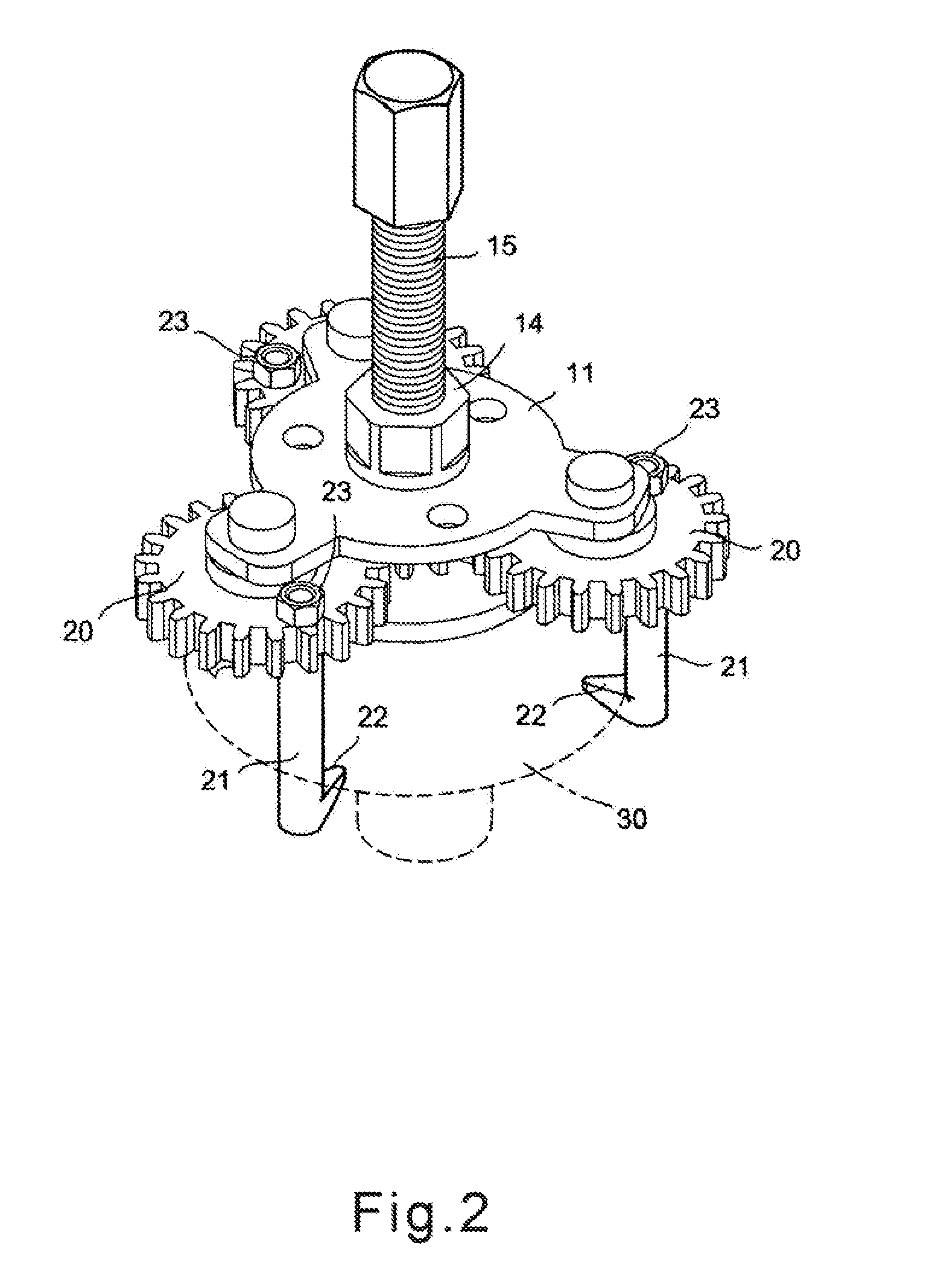
[0031]Please refer to FIGS. 6 and 7, in the present invention, each second driving element 20 includes a second driving portion and an arm 201. An outer peripheral face of the second driving portion annularly forms a plurality of protruding teeth to be engaged with the outer peripheral face of the first driving portion. The arm 201 extends from an end of the outer peripheral face, and an end of the clipping rod 21 is rotatably disposed on a free end of the arm 201. Thus, the second driving portion can be completely received in the receiving room between the upper and the lower shells, and the cover above the upper shell for safety is not necessary anymore.

[0032]Please refer to FIGS. 3 and 4 for operation in the major embodiment. When rotating the bolt 15 to directly or indirectly drive the axle portion, the first driving portion, and the second driving elements 20 to rotate, the clipping rods 21 are able to be driven to shift between a first position and a second position. In other ...


PUM

PropertyMeasurementUnit
timeaaaaaaaaaa
stabilityaaaaaaaaaa
shapeaaaaaaaaaa

Abstract

A drawing device of the present invention includes a first driving element, a bolt, a plurality of second driving elements, and a plurality of clipping rods. The first driving element drives the second driving elements to rotate simultaneously, so that the clipping rods are able to be rotated and operated. Also, a hook portion of each clipping rod is able to hook to a bottom of objects to be drawn out, and the bolt is disposed on a threaded hole of the first driving element and abuts against the objects to be drawn out. At the same time, the clipping rods are moved outward.

Description

BACKGROUND OF THE INVENTION[0001]1. Field of the Invention[0002]The present invention relates to drawing device.[0003]2. Description of the Prior Art[0004]A conventional drawing device is shown in FIGS. 8 and 9. A hook portion 44 of each of the two linkage rod 42 abuts against a side of an object 45 to be drawn out, and a bolt is screwed to abut against a fixed end 46 on which the object 45 is disposed. At the same time, relative to the bolt being screwed downward, a body 40 is moved upward and removes the object 45 from the fixed end 46.[0005]However, all the elements of the previous drawing device are linked together in a pivot manner, so that hooking to the bottom of the object and positioning are difficult. Also, an object in a narrow space is further difficult to be removed.[0006]Moreover, the two clipping rods 43 are arc-shaped and bent outward, so that the drawing device is hard to enter a narrow space to operate. Even if the drawing device is able to be placed into a narrow ...

Claims


Application Information

Patent Timeline
Patent Type & Authority Applications(United States)
IPC IPC(8): B23P19/04
CPCY10T29/53857B25B27/023Y10T29/53843
Inventor CHEN, LUNG-SHANCHEN, LIEN-CHINCHEN, CHING-FANG
Owner SHINE YEN IND
Why Eureka
Try Eureka