Wind turbine with channels and roof air exhaust

a wind turbine and air exhaust technology, applied in the direction of machines/engines, sustainable buildings, electric generator control, etc., can solve the problems of limiting the use of wind turbines in some areas, affecting the safety of the environment, so as to achieve high wind speed, reduce noise pollution, and create energy. the effect of alternating curren

Active Publication Date: 2015-04-21
BX POWER
View PDF10 Cites 10 Cited by
  • Summary
  • Abstract
  • Description
  • Claims
  • Application Information

AI Technical Summary

Benefits of technology

[0015]The enclosed turbine is very versatile in creating energy at unmatched low speeds of 2 mph vs. 8-14 mph with the traditional style turbines, as well as high wind speeds with little or no noise pollution. The enclosed turbine produces little to no air pressure at the top of the unit where the air exit location is, because the wind entering into the unit is being more completely used to create power. This turbine utilizes the housing structure to collect air through a large opening and funneling it to a smaller exit area, which increases the velocity of the air at the exit. The air exits substantially at the blades only.
[0016]As discussed above, the roof of the housing structure is designed to create negative airflow, known as stack effect. This aids in turning the rotor. The housing enhances the wind turbine in many ways. It protects the rotor and all the components from the environment, creating less required maintenance as well as ease of maintenance. The housing structure is built to provide easy access to all parts of the wind turbine. The housing also protects this turbine from the typical categories of environmental impact, visual, noise, and wildlife, and protects

Problems solved by technology

The height of the currently designed wind turbines limits their use in some areas, not only for aesthetics, but also because the exposed rotating blades are becoming a major concern for wildlife (such as birds).
There is a growing controversy about the number of birds being killed or maimed each and ev

Method used


Image

  • Wind turbine with channels and roof air exhaust
  • Wind turbine with channels and roof air exhaust
  • Wind turbine with channels and roof air exhaust

Examples


Embodiment Construction

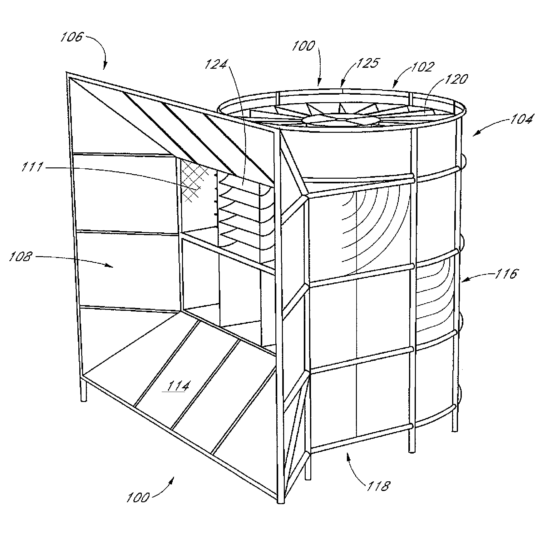
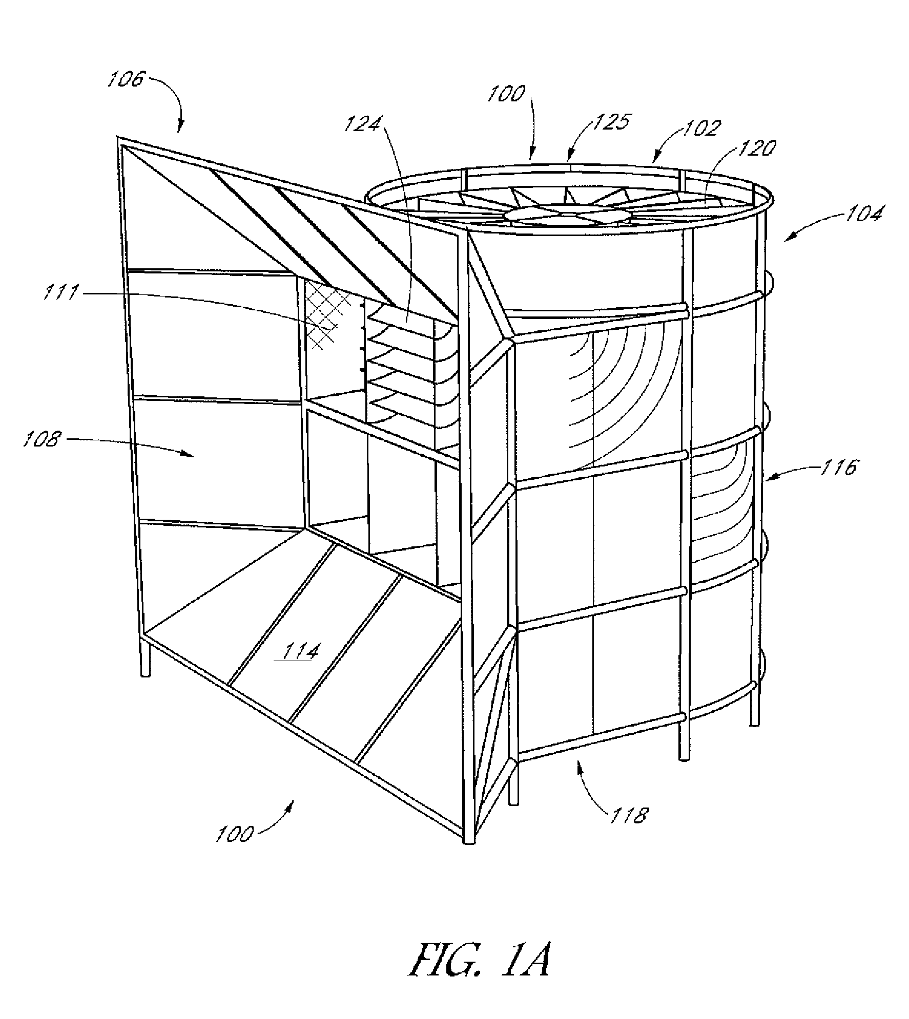
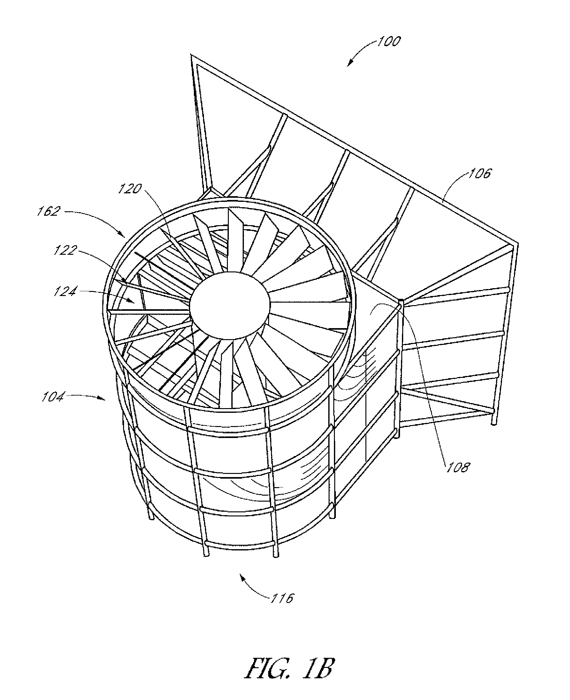
[0024]Reference will now be made to the drawings wherein like numerals refer to like parts throughout. As shown in FIGS. 1A-1B, a wind turbine 100 is formed such that a rotor assembly 102 is positioned within a housing 104. The housing 104 includes an air scoop opening assembly 106 that defines an opening 108 that directs air into a plurality of channels 110. As will be described in greater detail below, the channels 110 direct the air to different circumferential locations of the rotor assembly 102 so that force is more equally distributed against the rotor assembly 102.

[0025]In one implementation, the air scoop assembly 106 has an air scoop 112 that is comprised of four slanted walls that direct wind into the smaller dimensioned opening 108. In one non-limiting example, the air scoop 112 has exterior dimensions of approximately 12 to 15 feet high by 12 to 15 feet wide and has interior panels 114 that are angled at an angle of approximately 30 to 45 degrees. The interior panels 114...


PUM


Abstract

This wind turbine is enclosed in a housing structure with a bell shaped opening and a stack effect created on the roof. One side of the housing, facing the wind, opens up to receive air. The air that enters the housing is divided into multiple chambers. The chambers and turning vanes guide the air directly to the blades and help in minimizing air turbulence. The blades are angled to receive the maximum amount of the air. The air rotates the blades turning the rotor, converting mechanical rotation into electrical power. There is a horizontal rotor attached to vertical shaft which is used to generate electrical energy. The stack effect on the roof creates a negative air flow aiding in turning the rotor.

Description

INCORPORATION BY REFERENCE TO ANY PRIORITY APPLICATIONS[0001]Any and all applications for which a foreign or domestic priority claim is identified in the Application Data Sheet as filed with the present application are hereby incorporated by reference under 37 CFR 1.57. This Application claims the benefit of U.S. Provisional Application No. 61 / 673,675 filed Jul. 19, 2012.BACKGROUND OF THE INVENTION[0002]1. Field of the Invention[0003]The present invention relates to wind turbines and, in particular, to wind turbines that have reduced profiles and enclosed rotors that are environmentally more friendly.[0004]2. Description of the Related Art[0005]There is a long history of harnessing the power of wind to create energy and electricity. For example, in 1887 a windmill was constructed to generate power and charge batteries. The windmill and many like it have been made in the same tradition with a tall upright standing cylindrical structure with several large blades attached, designed to ...

Claims


Application Information

Patent Timeline
IPC IPC(8): F03B15/00F03D1/06F03D9/00
CPCF03D1/0608F03D9/002F03D1/04F05B2240/132F05B2240/133Y02B10/30F03D9/25F03D13/10F03D15/10F03D80/70Y02E10/72
Inventor CHARNESKY, CRAIGCANTU, BRIDGET
Owner BX POWER
Why Eureka
Try Eureka