
Turbomachine component, particularly a gas turbine engine component, with a cooled wall and a method of manufacturing

a technology of a turbine engine and a cooling wall, which is applied in the direction of machines/engines, manufacturing tools, light and heating apparatus, etc., can solve the problems that the material used in the typical gas turbine engine cannot withstand temperatures above 800° c, and reduce the efficiency of the gas turbine engin

Inactive Publication Date: 2017-10-12
SIEMENS AG
View PDF0 Cites 19 Cited by
  • Summary
  • Abstract
  • Description
  • Claims
  • Application Information

AI Technical Summary

Benefits of technology

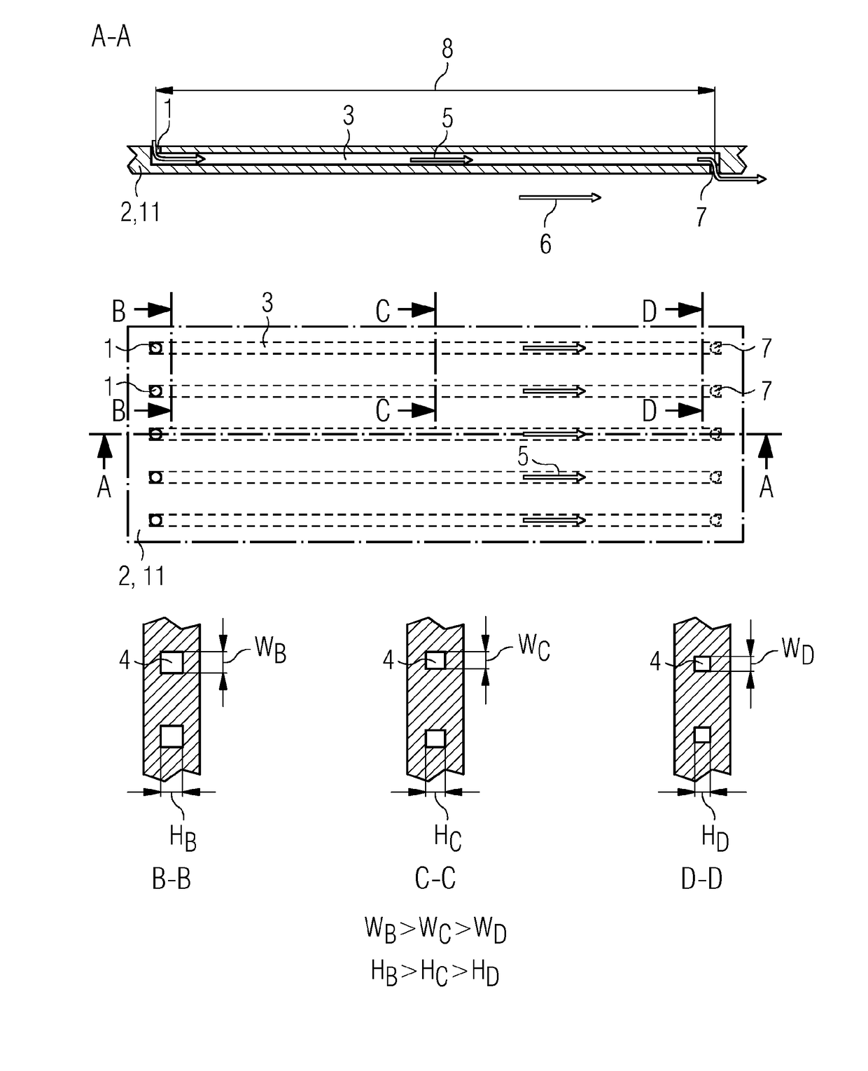
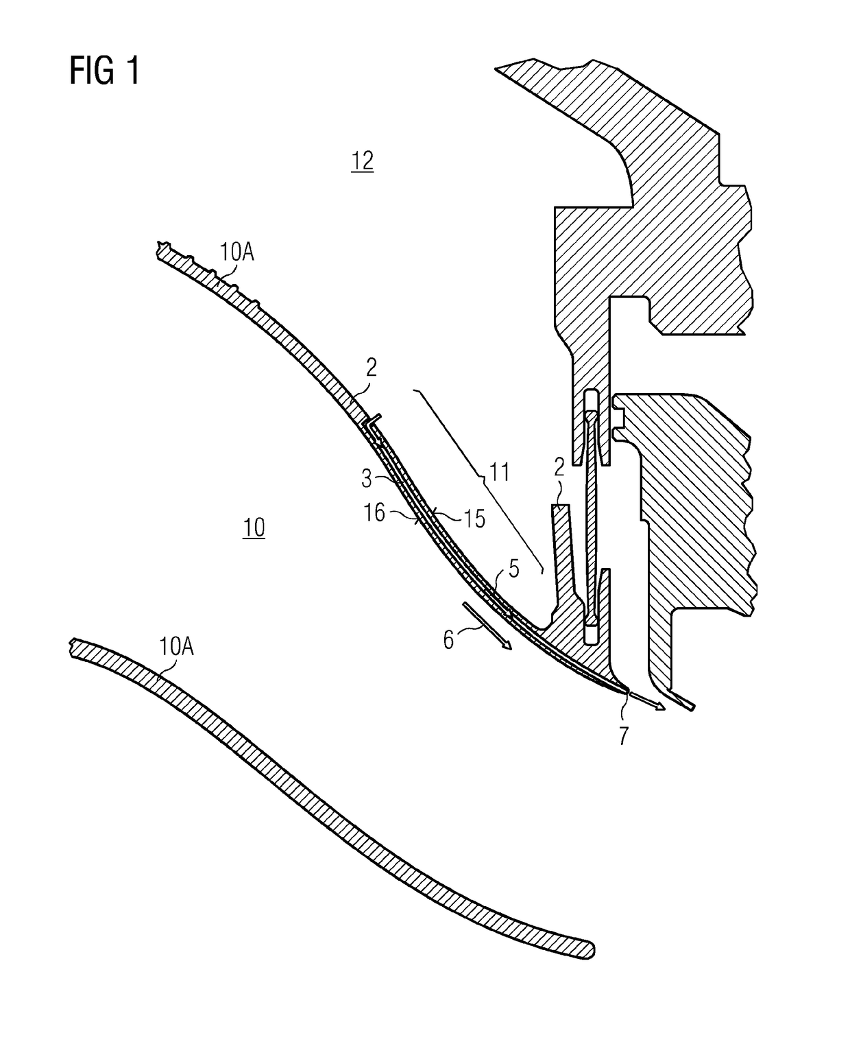
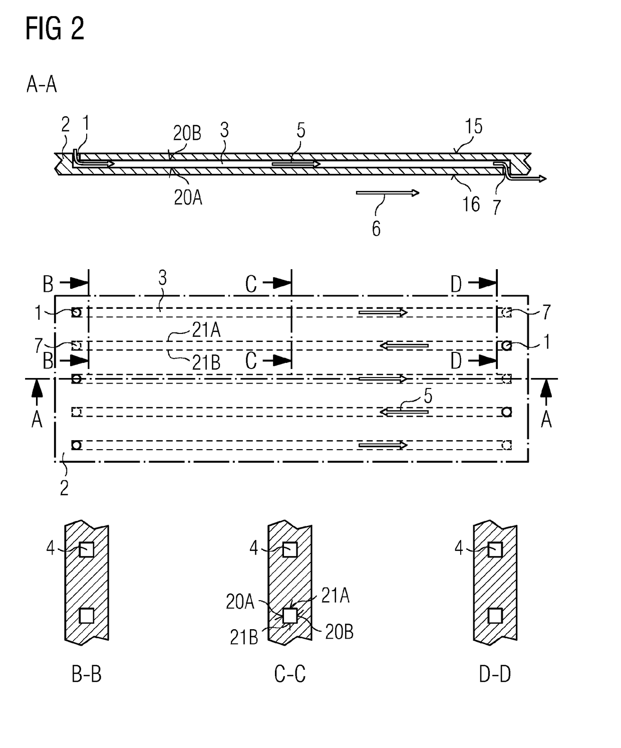
The patent describes a cooling system for metal parts that helps to control the heat transfer coefficient and maintain a constant cooling effect. The system uses a tapering design for the cooling channels, which allows for individual control of the cooling air velocity and heat transfer coefficient. The tapering also compensates for changes in air temperature and contact area, up to a certain level. The cooling channels can be built using laser sintering or laser melting, allowing for precise changes in cross-section and individual tapering of the channels. The system can also be designed to keep the width of the cooling channels constant and only change the height, so as not to negatively impact the cooling effect. The individual tapering of the cooling channels provides improved control over the heat transfer and cooling process, resulting in improved performance and efficiency of the cooling system.

Problems solved by technology

The temperatures can be up to 1,500° C. Nevertheless, materials used typically in a gas turbine engine cannot withstand temperatures above 800° C. Therefore, these components may need to be cooled or a specific coating is required to protect the component.
The provision of cooling functionality on the other hand reduces the efficiency of the gas turbine engine.

Method used


Image

  • Turbomachine component, particularly a gas turbine engine component, with a cooled wall and a method of manufacturing
  • Turbomachine component, particularly a gas turbine engine component, with a cooled wall and a method of manufacturing
  • Turbomachine component, particularly a gas turbine engine component, with a cooled wall and a method of manufacturing

Examples


Embodiment Construction

[0046]The illustrations in the drawings are schematical. It is noted that for similar or identical elements in different figures, the same reference signs will be used to denote the same or equivalent features.

[0047]Some of the features and especially the advantages will be explained for an assembled gas turbine, but obviously the features can be applied also to single components of the gas turbine but may show the advantages only once assembled and during operation. But when explained by means of a gas turbine during operation none of the details should be limited to a gas turbine solely while in operation. As the invention is inspired to counteract problems of combustion processes, the features can also applied to different types of machines that comprise a combustor of a different type, e.g. a combustor that operates with different types of fuels differing from gas and / or oil typically provided to a gas turbine combustor.

[0048]A gas-turbine engine may serve as one example of a ro...


PUM

PropertyMeasurementUnit
Fractionaaaaaaaaaa
Fractionaaaaaaaaaa
Temperatureaaaaaaaaaa

Abstract

A turbomachine component, particularly a gas turbine engine component, has at least one part built in parts from a curved or planar panel, particularly a sheet metal, the part having a plurality of cooling channels via which a cooling fluid, particularly air, is guidable, wherein at least one of the plurality of cooling channels has a continuously tapered section. The at least one of the plurality of cooling channels has a single inlet port from a first surface of the panel and a single outlet port for the cooling fluid to another surface, particularly a surface opposite to the first surface, or to the first surface. Further the panel is built via laser sintering or laser melting or direct laser deposition. A gas turbine engine is equipped with such a component. A method of manufacturing includes incorporating cooling channels having a continuously tapered section.

Description

CROSS REFERENCE TO RELATED APPLICATIONS[0001]This application is the US National Stage of International Application No. PCT / EP2015 / 071833 filed Sep. 23, 2015, and claims the benefit thereof. The International Application claims the benefit of European Application No. EP14187066 filed Sep. 30, 2014. All of the applications are incorporated by reference herein in their entirety.FIELD OF THE INVENTION[0002]The invention relates to a turbomachine (or rotating machine) component, particularly a gas turbine engine component in a hot region of a gas turbine engine, in which cooling channels are present to cool a hot surface.BACKGROUND OF THE INVENTION[0003]Gas turbine engines like other rotating machines comprise sections wherein a cool fluid is guided and other regions in which a hot fluid is guided through the engine. In the gas turbine engine typically ambient air as a fairly cool fluid may be compressed by a compressor section and provided to a combustor in which the substantially cool...

Claims


Application Information

Patent Timeline
IPC IPC(8): F01D9/02B23K26/21F02K1/82F23R3/00F01D25/12F01D25/14
CPCF01D9/023F01D25/12F01D25/14F02K1/822F23R3/002F23R2900/03041F01D25/08F01D25/24F02K1/82F05D2260/20F05D2260/202B23K26/21F23R3/005F23R2900/03042F05D2230/22F05D2250/292F05D2230/54F05D2260/203Y02P10/25Y02T50/60
Inventor LORSTAD, DANIELOFVERSTEDT, TOMAS
Owner SIEMENS AG
Learn More