Rotary joint

A technology of rotating joints and contact surfaces, applied in the direction of pipes/pipe joints/fittings, adjustable connections, passing components, etc., to achieve the effect of ensuring free rotation, reliable sealing, and reducing wear

Active Publication Date: 2014-02-05
AEROSUN CORP
View PDF5 Cites 10 Cited by
  • Summary
  • Abstract
  • Description
  • Claims
  • Application Information

AI Technical Summary

Problems solved by technology

[0004] The purpose of the present invention is to propose a rotary joint that can maintain reliable sealing while ensuring free rotation in view of the problems existing in the existing rotary joint under high temperature and high pressure conditions.

Method used


Image

  • Rotary joint
  • Rotary joint
  • Rotary joint

Examples


Embodiment Construction

[0019] The present invention will be further described below in conjunction with accompanying drawing.

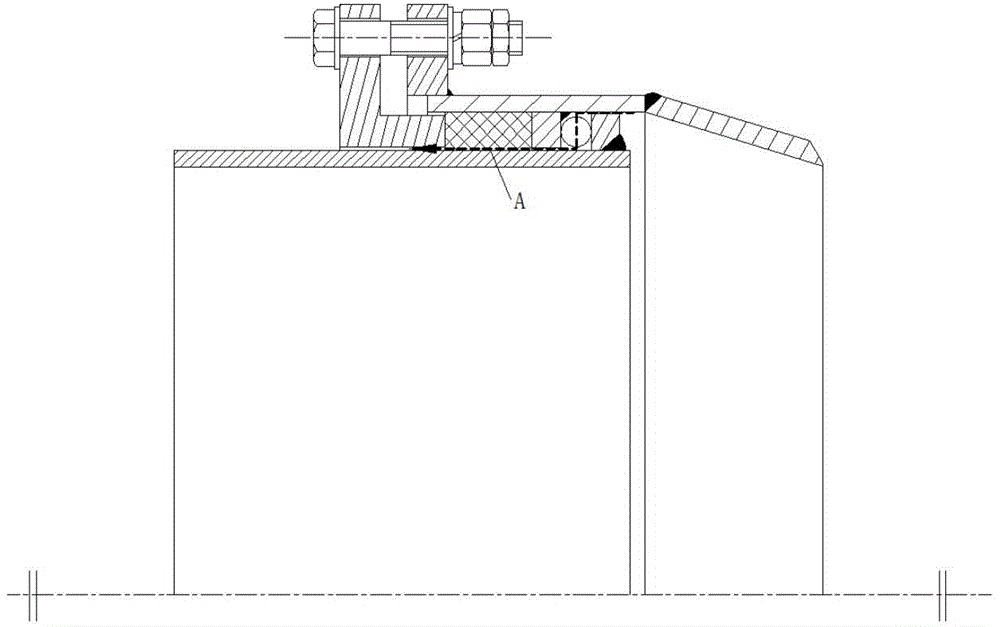
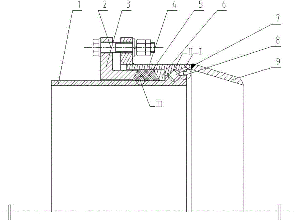
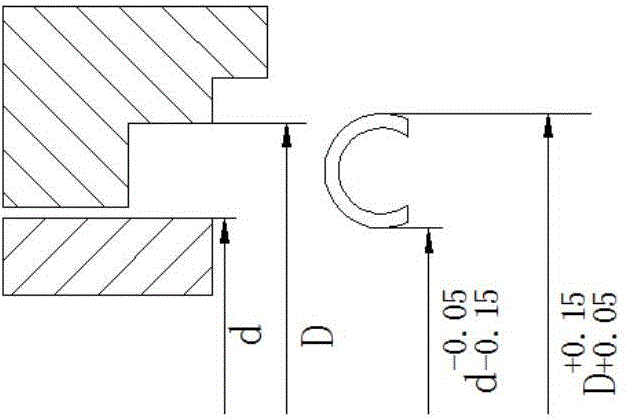
[0020] The high-temperature, high-pressure, low-friction rotary joint of this embodiment is as follows: figure 2 As shown, one end of the outer pipe 4 is welded with a radially extending connecting flange, and the other end is welded with a tapered reducing pipe 9, the inner pipe 1 is inserted into the outer pipe 4 from the end of the connecting flange, and the inner end of the gland 3 is inserted into the outer pipe 4 and Between the inner pipes 1, and its outer end is connected with the connecting flange of the outer pipe through radially extending flanges by means of bolts 2 evenly distributed around the circumference. The outer tube 4 has a radially contracted inner convex ring adjacent to the reducing tube 9, and the inner tube 1 has an outer convex ring corresponding to the position of the inner convex ring. The inner convex ring and the outer convex ring have openin...


PUM


Abstract

The invention relates to a rotary joint and belongs to the technical field of heat power pipe network matching. The joint comprises an outer pipe, an inner pipe and a gland, wherein an inner convex ring is arranged inside the outer pipe, an outer convex ring is arranged outside the inner pipe, the inner convex ring and the outer convex ring are respectively provided with V-shaped grooves of which openings are opposite, and obliquely-arranged cylindrical rollers are mounted inside the V-shaped grooves; one end of the inner convex ring adopts an expanding section with an annular space, and a C-shaped elastic metal sealing ring is embedded into the annular space; a trapezoidal baffle ring with an inclined plane at one end is mounted at the other end of the inner convex ring, the inner end of the gland adopts an inclined plane which is opposite to the inclining direction of the trapezoidal baffle ring, and a graphite filling material sealing ring is mounted between the trapezoidal baffle ring and the gland. After the adoption of the invention, the C-shaped elastic metal sealing ring and the graphite filling material sealing ring form high-temperature resistant and high-voltage resistant double sealing, the arranged direction of a bearing and the trapezoidal cross section graphite filling material sealing ring form a reasonable force bearing system. Therefore, the rotary joint provided by the invention has remarkable advantages that reliable sealing under high-temperature and high-voltage conditions is kept while free rotation can be ensured.

Description

technical field [0001] The invention relates to a rotary joint, in particular to a low-friction rotary joint resistant to high temperature and high pressure, and belongs to the technical field of supporting heat pipe networks. Background technique [0002] In the industrial heat pipe network, the traditional bellows expansion joints and sleeve expansion joints currently widely used have problems such as poor pressure bearing capacity, small compensation amount, easy leakage, small angular compensation amount, and easy settlement. Therefore, the rotational displacement can be used to achieve As a new type of pipeline joint, the rotary joint with thermal compensation effect is gradually replacing the above traditional joints. [0003] The structure of the existing rotary joint (also known as rotary compensator) is as follows figure 1 As shown, although it not only has the performance of traditional expansion joints, but also has the characteristics of long-distance transmissi...

Claims


Application Information

Patent Timeline
Patent Type & Authority Applications(China)
IPC IPC(8): F16L27/08
CPCF16L27/0832
Inventor 陈为柱尚丽娟宋丰懿金南
Owner AEROSUN CORP
Why Eureka
Try Eureka