Heat exchanger

A technology of heat exchangers and heat exchange tubes, which is applied in the direction of heat exchanger types, indirect heat exchangers, heat exchange equipment, etc., and can solve problems such as flow channel deformation and blockage of heat exchange tubes

Inactive Publication Date: 2020-10-27
ZHEJIANG SANHUA INTELLIGENT CONTROLS CO LTD
View PDF11 Cites 2 Cited by
  • Summary
  • Abstract
  • Description
  • Claims
  • Application Information

AI Technical Summary

Problems solved by technology

[0002] Automobiles, household or commercial air-conditioning systems all need to use heat exchange devices. One solution in the related art is that the heat exchanger includes integrated heat exchange tubes and heat exchange plates. In order to meet the heat exchange performance, the integrated heat exchange tubes and heat exchange plates when designing multiple refrigeration circuits, such as figure 1 As shown, the heat exchange tube integrated with the heat exchange plate needs to be bent multiple times to make the refrigerant flow through the heat exchange tube 20 longer, thereby increasing the amount of heat exchange between the refrigerant and the air. However, in the related art The flow of multiple refrigerants is mainly achieved by multiple bending of the heat exchange tube itself at a large angle. Bending the heat exchange tube at a large angle can easily cause deformation or even blockage of the flow channel of the heat exchange tube.

Method used


Image

  • Heat exchanger
  • Heat exchanger
  • Heat exchanger

Examples


Embodiment Construction

[0029] The following will clearly and completely describe the technical solutions in the embodiments of the present application with reference to the accompanying drawings in the embodiments of the present application. Obviously, the described embodiments are only part of the embodiments of the present application, not all of them. Based on the embodiments in this application, all other embodiments obtained by persons of ordinary skill in the art without creative efforts fall within the protection scope of this application.

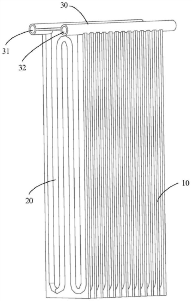
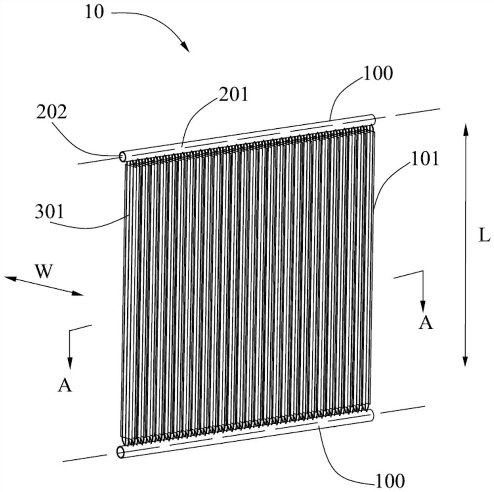
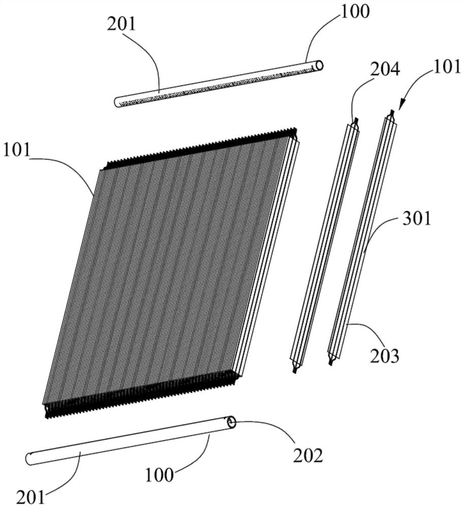
[0030] see figure 2 and image 3 , the present application provides a heat exchanger 10 , which includes a header set and a plurality of heat exchange components 101 . The header set includes two headers 100 respectively located on both sides of the heat exchange component 101 in the length direction, and each header 100 includes a longitudinal tube body 201 and a header cavity 202 . The length direction of the heat exchange assembly 101 is figure 2 ...


PUM


Abstract

The invention discloses a heat exchanger. The heat exchanger comprises a plurality of collecting pipes and a plurality of heat exchange assemblies; in the axial direction of the collecting pipes, theheat exchange assemblies are arranged at intervals; each heat exchange assembly comprises a fin plate and a plurality of heat exchange pipes; the heat exchange pipes of the heat exchange assemblies are divided into at least two groups in the width direction of the heat exchange assemblies, the number of each group of heat exchange pipes is at least one, and each group of heat exchange pipes is connected between the two collecting pipes; for the heat exchange pipes of the two adjacent groups, the inner cavities of the heat exchange pipes of the two groups respectively communicate with the innercavities of the two different collecting pipes on one side; and the inner cavities of the heat exchange pipes of the two groups communicate with the inner cavity of the same collecting pipe on the other side, or the inner cavities of the heat exchange pipes of the two groups respectively communicate with the inner cavities of the two different collecting pipes on the other side, and the inner cavities of the two collecting pipes on the other side communicate with each other, so that the flowing directions of a refrigerant in the inner cavities of the heat exchange pipes of the two groups areopposite. The heat exchange performance of the heat exchanger is improved.

Description

technical field [0001] The present application relates to the field of heat exchange, in particular to a heat exchanger. Background technique [0002] Automobiles, household or commercial air-conditioning systems all need to use heat exchange devices. One solution in the related art is that the heat exchanger includes integrated heat exchange tubes and heat exchange plates. In order to meet the heat exchange performance, the integrated heat exchange Tubes and heat exchange plates are designed for multiple refrigeration circuits, such as figure 1 As shown, the heat exchange tube integrated with the heat exchange plate needs to be bent multiple times to make the refrigerant flow through the heat exchange tube 20 longer, thereby increasing the amount of heat exchange between the refrigerant and the air. However, in the related art Multiple refrigerant flow return journeys are mainly achieved by multiple bending of the heat exchange tube itself at a large angle. Bending the hea...

Claims


Application Information

Patent Timeline
Patent Type & Authority Applications(China)
IPC IPC(8): F28D1/053F28F1/22
CPCF28D1/05316F28F1/22
Inventor 王立智蒋皓波蒋建龙李永平李炅
Owner ZHEJIANG SANHUA INTELLIGENT CONTROLS CO LTD
Why Eureka
Try Eureka