
Orthopaedic traction frame for medical orthopedics department

An orthopaedic traction frame and medical frame technology, applied in the field of medical machinery, can solve the problems of inability to effectively associate the joint area and the foot area, insufficient overall operation stability, etc., and achieve the effect of improving the medical rehabilitation effect and improving the rehabilitation effect.

Inactive Publication Date: 2020-10-30
丘兰英
View PDF1 Cites 0 Cited by
  • Summary
  • Abstract
  • Description
  • Claims
  • Application Information

AI Technical Summary

Problems solved by technology

[0004] Chinese patent (authorized announcement number: CN109602527A) discloses an orthopedic traction frame for medical orthopedics. This application helps the user's legs not to be moved arbitrarily when doing traction exercises, but this patent has certain defects. Insufficient stability and inability to effectively associate the joint area with the foot area

Method used


Image

  • Orthopaedic traction frame for medical orthopedics department
  • Orthopaedic traction frame for medical orthopedics department
  • Orthopaedic traction frame for medical orthopedics department

Examples


Embodiment 1

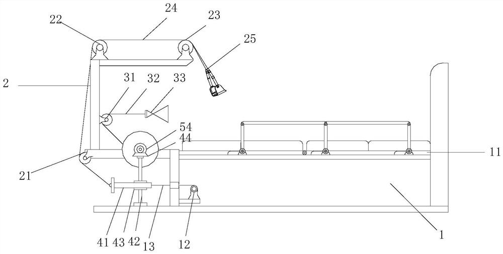
[0028] see figure 1 , an orthopedic traction frame for medical orthopedics, comprising a nursing bed 1 and a medical frame 2, the medical frame 2 is installed at the end of the nursing bed 1, the nursing bed 1 is provided with a bearing bed board 11, the medical frame The top of 2 is equipped with second direction changing wheel 22 and the third direction changing wheel 23, and the bottom corner position of described medical stand 2 is equipped with first direction changing wheel 21, and described first direction changing wheel 21, second direction changing wheel A first front traction line 24 is arranged between the wheel 22 and the third direction-changing wheel 23, the end of the first front traction line 24 is equipped with a knee sleeve 25, and the inner cavity of the nursing bed 1 is provided with a backguy Roller 12, the first rear pulling wire 13 is wound on the wire pulling roller 12, the first front pulling wire 24 is connected with the first rear pulling wire 13, an...

Embodiment 2

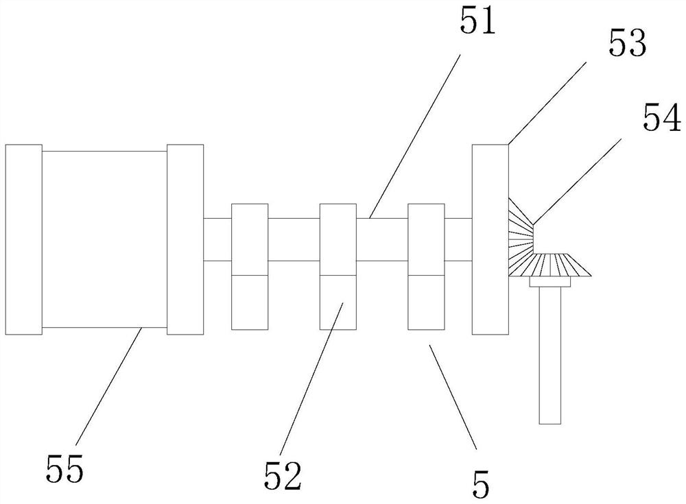
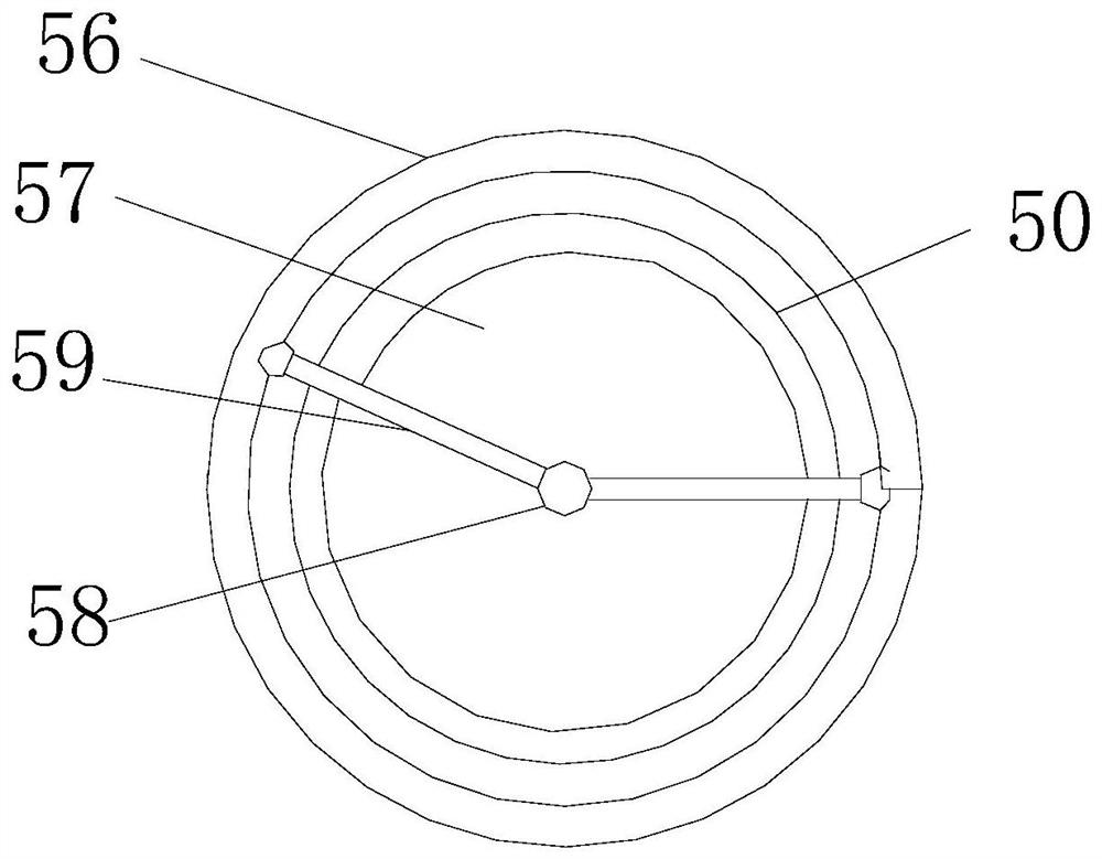
[0035]see image 3 and Figure 4 , this embodiment is a further optimization of Embodiment 1. On the basis of this, the external turntable 55 is a cylinder frame structure, the axis position of the external turntable 55 is provided with a central axis 58, and the outer turntable 55 The inner cavity is provided with a built-in roller 57, and the outer wall of the outer turntable 55 is provided with an outer roller 56. The central shaft 58 rotates, and the length of the built-in drum 57 is wound with a coil spring 50 , one end of the coil spring 50 is connected with the built-in drum 57 , and the other end of the coil spring 50 is fixed on the outer drum 56 .

[0036] The present application can also be provided with the external turntable 55 as a cylinder frame structure, and a coil spring 50 is arranged between the external drum 56 and the built-in drum 57. Through the twisting force of the coil spring 50, the effect of elastic reset is achieved, thereby It can have the effe...


PUM


Abstract

The invention relates to the field of medical machinery, and relates to an orthopaedic traction frame for medical orthopedics department. The device comprises a nursing bed and a medical frame, a wirepulling roller is arranged in an inner cavity of the nursing bed; a first rear pull wire is wound on the wire drawing roller; a knee lapping sleeve is mounted at the tail end of a first front pull wire; the first rear pull wire is externally connected with the first front pull wire, a built-in turning wheel is installed on the medical frame, a second pull wire is erected on the built-in turning wheel, the tail end of the second pull wire is connected with a foot sleeve, and a transmission rack is connected between the first front pull wire and the first rear pull wire. The associated transmission is carried out between a foot sleeve and the knee lapping sleeve, and the medical rehabilitation effect on a patient is improved.

Description

technical field [0001] The invention relates to the field of medical machinery, in particular to an orthopedic traction frame for medical orthopedics. Background technique [0002] Medical devices refer to instruments, equipment, utensils, in vitro diagnostic reagents and calibrators, materials, and other similar or related items that are directly or indirectly used on the human body, including required computer software. The utility is mainly obtained through physical means, and its purpose is the diagnosis, prevention, monitoring, treatment or alleviation of diseases; the diagnosis, monitoring, treatment, alleviation or functional compensation of injuries; the inspection, replacement, adjustment or support of physiological structures or physiological processes; support or maintenance of pregnancy; pregnancy control; providing information for medical or diagnostic purposes by examining samples from humans. [0003] Bone traction is one of the orthopedic treatment methods f...

Claims


Application Information

Patent Timeline
IPC IPC(8): A61F5/042
CPCA61F5/042
Inventor 丘兰英
Owner 丘兰英
Features
  • Generate Ideas
  • Intellectual Property
  • Life Sciences
  • Materials
  • Tech Scout
  • Unparalleled Data Quality
  • Higher Quality Content
  • 60% Fewer Hallucinations
Learn More