High-precision hydraulic balance detection supporting table

A hydraulically balanced, high-precision technology that can be used in static/dynamic balance testing, measuring devices, machine/structural component testing, etc., and can solve problems such as unstable adjustment amplitudes

Inactive Publication Date: 2020-10-30
宣城知明灯机械设计有限公司
View PDF0 Cites 4 Cited by
  • Summary
  • Abstract
  • Description
  • Claims
  • Application Information

AI Technical Summary

Problems solved by technology

[0004] Based on the technical problem that the existing high-precision hydraulic balance detection support table is unstable when the adjustment range is too large, the present invention proposes a high-precision hydraulic balance detection support table

Method used


Image

  • High-precision hydraulic balance detection supporting table
  • High-precision hydraulic balance detection supporting table
  • High-precision hydraulic balance detection supporting table

Examples


Embodiment 1

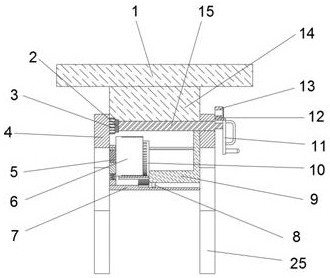
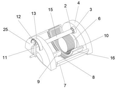
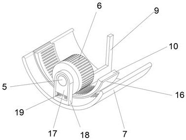
[0027] Reference Figure 1-3 with Figure 5 , A high-precision hydraulic balance detection support table, including a connecting table 14, the top outer wall of the connecting table 14 is connected with a table plate 1 through bolts, a support shaft 15 is inserted into the wall of the connecting table 14, and a rotating mechanism is fixed on one side of the support shaft 15 , The other side of the support shaft 15 is fixed with the limit mechanism, the outer walls on both sides of the connecting platform 14 are respectively connected by sliding legs with leg one 4 and leg two 25, and there is a tooth groove between the leg one 4 and the leg two 25 through bolts. The arc plate 7 is provided with a card slot in the wall of the tooth slot arc plate 7, a measuring mechanism is fixed on one side of the second leg 25, a slow motion mechanism is fixed on the outer wall of the tooth slot arc plate 7, and a locking mechanism is fixed on the outer wall of the support shaft 15.

[0028] In ...

Embodiment 2

[0036] Reference Figure 4 with Figure 5 , A high-precision hydraulic balance detection support table. Compared with the first embodiment, this embodiment also includes a movable rod 22 plugged into the top of the first leg 4 and the second leg 25, and the top outer wall of the movable rod 22 is connected by bolts. The roller 21, and the top of the roller 21 is in contact with the outer wall of the bottom of the table board 1, and the inner walls of the legs 4 and 25 are connected with a transmission hose 23 by sliding. The outer wall of the transmission hose 23 is connected by a bolt with an extension support The inner walls of the plate 20, the first leg 4 and the second leg 25 are all connected to the extension support plate 20 by a return spring 26 through bolts.

[0037] When in use, when the adjustment range of the table board 1 is too large, the center of gravity of the table board 1 will move to one side when the table board 1 is loaded. At this time, the roller 21 is pre...


PUM


Abstract

The invention discloses a high-precision hydraulic balance detection supporting table. Aiming at the problem that the overall stability of a device is not high because the adjusting amplitude is too large, the following scheme is presented that the supporting table comprises a connecting table, wherein the outer wall of the top of the connecting table is connected with a table plate through bolts,a supporting shaft is inserted into the wall of the connecting table, a rotating mechanism is fixed to one side of the supporting shaft, a limiting mechanism is fixed on the other side of the supporting shaft, and the outer walls of the two sides of the connecting table are respectively and slidably connected with a first supporting leg and a second supporting leg. According to the supporting table, the angle of the table plate is adjusted by rotating a rocking handle, a rotating plate and the supporting shaft are moved by pushing a pull handle, a positioning tooth moves into a tooth sleeve,due to the large volume of tooth pieces of the positioning tooth in the tooth sleeve, and the tooth sleeve has a coarse positioning effect on the positioning tooth; and pushing is continued, a toothedplate on an L-shaped clamping plate is engaged with a tooth groove in a tooth groove arc plate, the fixing effect is achieved, the angle of the table plate is conveniently adjusted, and the device ismore stable in the adjusting process.

Description

Technical field [0001] The invention relates to the technical field of support devices, in particular to a high-precision hydraulic balance detection support table. Background technique [0002] Hydraulic balance is a balance method that uses hydraulic pressure to balance the load (including the equipment itself). In some industrial production, the workbench required to be used is horizontal, which makes the results in the test more stable and obtains more accurate data. A good working test environment, and the existing devices cannot even achieve the level in some cases, resulting in poor device effectiveness and unfavorable use. [0003] The existing high-precision hydraulic balance detection support table is not stable enough when the adjustment range is too large, and the device shakes greatly under the influence of the external environment, which makes the device prone to deviation during hydraulic pressure detection, resulting in inaccurate detection results and affecting the...

Claims


Application Information

Patent Timeline
Patent Type & Authority Applications(China)
IPC IPC(8): B25H1/02B25H1/18B25H1/00G01M1/02
CPCB25H1/00B25H1/02B25H1/18G01M1/02
Inventor 郝明明伍俊峰吴飞亚
Owner 宣城知明灯机械设计有限公司
Why Eureka
Try Eureka