Rigid-flexible coupling airborne loading combined buffering device

A technology of rigid-flexible coupling and cushioning devices, which is applied in launching devices, transportation and packaging, and aircraft parts, and can solve problems such as equipment damage, single structure, and airbag explosion

Inactive Publication Date: 2020-10-30
CHANGSHA UNIVERSITY OF SCIENCE AND TECHNOLOGY
View PDF9 Cites 0 Cited by
  • Summary
  • Abstract
  • Description
  • Claims
  • Application Information

AI Technical Summary

Problems solved by technology

However, this type of airborne device always has the problem that the airdropped materials directly touch the ground or rebound or even overturn, which causes great damage to the equipment, and cannot guarantee the accuracy of the landing site, especially when it cannot adapt to bad weather and complex landing terrain. airborne
[0005] 2. In order to overcome the problem that the airdrop equipment directly touches the ground, a small number of existing technologies design an anti-turnover device on the airborne device and set a buffer protective airbag at the bottom of the equipment, but the buffer protective airbag arranged at the bottom of the device is easily caught by the ground when it touches the ground. Piercing by sharp objects causes the airbag to deflate or the internal pressure of the airbag is too high to cause the airbag to burst, which will cause fatal damage to the airdropped materials
[0006] 3. Most of the existing load airborne buffer devices use airbag buffer devices, and most of them are single-chamber airbag buffer devices with a single structure. There are no other forms of buffer devices, resulting in limited effective buffer strokes and buffer forms. Therefore, Can't play a good buffer effect on airborne materials

Method used


Image

  • Rigid-flexible coupling airborne loading combined buffering device
  • Rigid-flexible coupling airborne loading combined buffering device
  • Rigid-flexible coupling airborne loading combined buffering device

Examples


Embodiment Construction

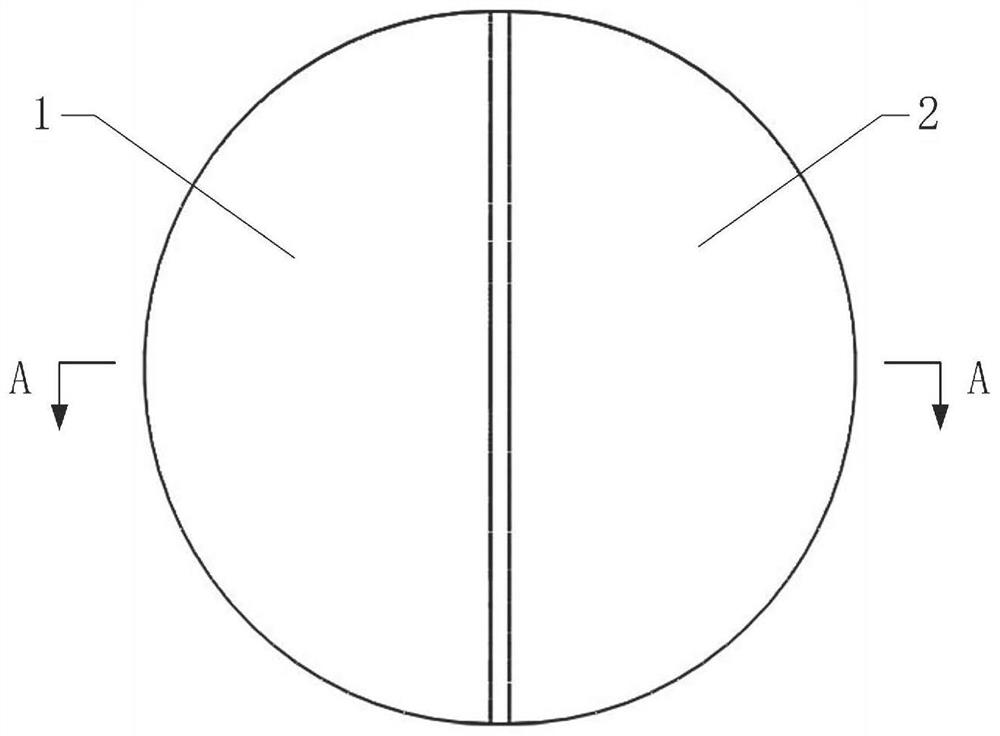
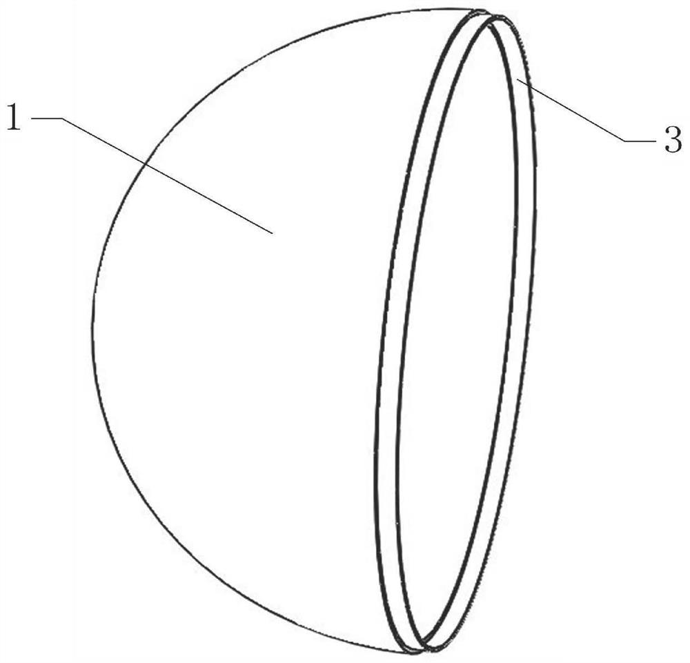
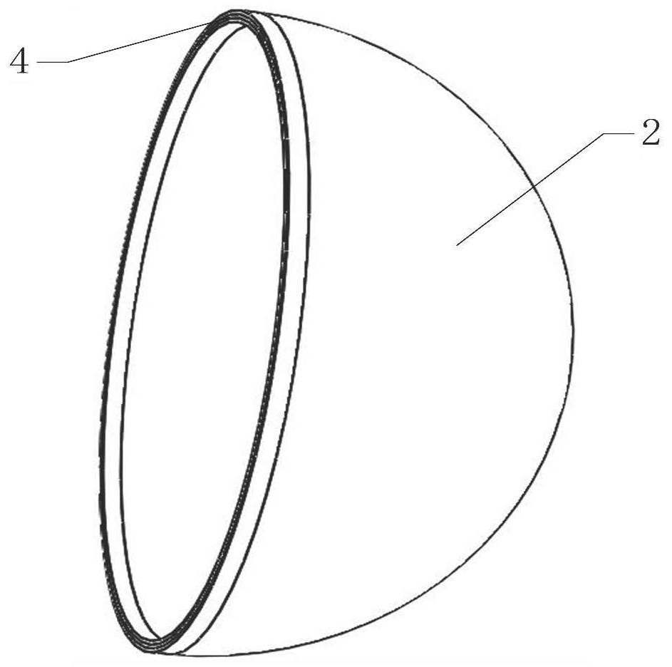
[0041]As shown in the figure: a rigid-flexible coupled airborne load combined buffer device, the overall shape of the rigid-flexible coupled airborne load combined buffer device is spherical, including an airborne material storage box 5, an inner buffer airbag 7, an inner ball Shell, outer buffer airbag 14 and outer spherical shell; the airborne material storage box 5, inner buffer airbag 7, inner spherical shell, outer buffer airbag 14 and outer spherical shell are arranged in a manner of wrapping airborne materials layer by layer from inside to outside The surface of the airborne material storage box 5 and the inner surface of the inner spherical shell are evenly arranged with eight connecting rings 16; the connecting rings 16 arranged on the described airborne material storage box 5 are connected with the inner surface of the inner spherical shell The rings 16 are in one-to-one correspondence, and the middle sections of every pair of corresponding connecting rings 16 are on ...


PUM


Abstract

The invention discloses a rigid-flexible coupling airborne cargo combined buffering device. The device is arranged in the mode that airborne materials are wrapped layer by layer from inside to outsidethrough an airborne cargo storage box, an inner buffering air bag, an inner spherical shell, an outer buffering air bag and an outer spherical shell. The storage box is connected with the inner spherical shell by hooking each pair of corresponding connecting rings through a plurality of buffer springs; the inner buffer air bag is arranged in a gap between the material storage box and the inner spherical shell; the outer buffer air bag is arranged in a gap between the inner spherical shell and the outer spherical shell; the inner spherical shell and the outer spherical shell are each composedof two semispherical half shells and are assembled through a clamping structure composed of clamping grooves in the two semispherical shells and clamping keys. By means of the layer-by-layer wrappingmode, multi-stage buffering of the airborne materials can be achieved, the all-around buffering protection of the materials can be achieved through the spherical design, and therefore, the attitude requirement of the airborne device for landing is lowered, and the capacity of adapting to severe weather and complex landing terrain airborne landing is enhanced.

Description

technical field [0001] The invention relates to the field of airborne safety protection for loaded objects, in particular to a rigid-flexible coupled airborne loaded combined buffer device. Background technique [0002] Loading airborne is to airdrop the required materials to the destination, which has great practical significance in aspects such as military affairs and earthquake relief. Since the airborne materials will bear a huge impact load on the ground at the moment of landing, in order to ensure the safe landing of the airborne materials for the subsequent use of the airborne materials by the ground receiving personnel, protective buffer devices must be used to reduce the damage to the materials caused by the impact load. [0003] In the actual loading airborne landing process, the following problems exist in the existing loading airborne device: [0004] 1. Most of the existing load-carrying airborne devices use large-area parachutes to decelerate the materials so ...

Claims


Application Information

Patent Timeline
Patent Type & Authority Applications(China)
IPC IPC(8): B64D1/08B64D1/14F16F15/023F16F15/067F16F15/04
CPCB64D1/08B64D1/14F16F15/023F16F15/067F16F15/046
Inventor 刘鑫李天睿周振华胡林陈德黄雷
Owner CHANGSHA UNIVERSITY OF SCIENCE AND TECHNOLOGY
Why Eureka
Try Eureka