Working method of airborne load combination buffer device with gas liquid solid coupling

A buffer device and working method technology, applied in the direction of launching devices, transportation and packaging, aircraft parts, etc., can solve the problems of airdrop material damage, large rebound, and inability to adapt to airborne, etc., and achieve the effect of reducing requirements and enhancing capabilities

Inactive Publication Date: 2020-10-30
CHANGSHA UNIVERSITY OF SCIENCE AND TECHNOLOGY
View PDF10 Cites 0 Cited by
  • Summary
  • Abstract
  • Description
  • Claims
  • Application Information

AI Technical Summary

Problems solved by technology

However, this type of airborne device always has the problem that the airdropped equipment directly touches the ground or rebounds or even overturns, which will cause great damage to the materials, especially the airborne that cannot adapt to bad weather and complex landing terrain.
[0005] 2. In order to overcome the problem that the airdrop device directly touches the ground, a small part of the prior art designs an anti-turnover device on the airborne device and arranges a buffer protective airbag at the bottom of the device, but the buffer protective airbag arranged at the bottom of the device is easily caught by the ground when it touches the ground. Piercing by sharp objects causes the airbag to deflate or the internal pressure of the airbag is too high to cause the airbag to burst, which will cause fatal damage to the airdropped materials
[0006] 3. Most of the existing load airborne buffer devices use airbag buffer devices, and most of them are single-chamber airbag buffer devices with a single structure. There are no other forms of buffer devices, resulting in limited effective buffer strokes and buffer forms. Therefore, Can't play a good buffer effect on airborne materials

Method used


Image

  • Working method of airborne load combination buffer device with gas liquid solid coupling
  • Working method of airborne load combination buffer device with gas liquid solid coupling
  • Working method of airborne load combination buffer device with gas liquid solid coupling

Examples


Embodiment Construction

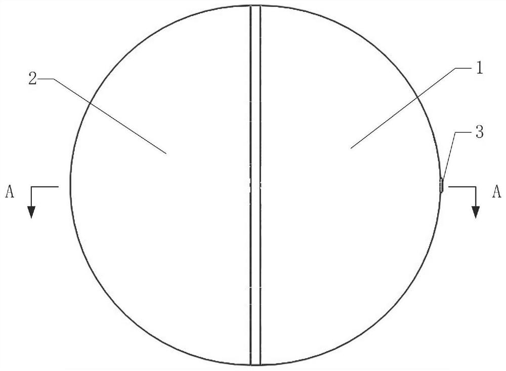
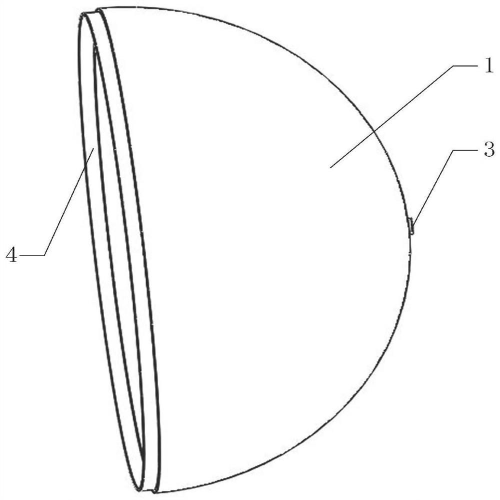
[0031] As shown in the figure: a working method of a gas-liquid-solid coupled airborne load combined buffer device, the overall shape of the gas-liquid-solid coupled airborne load combined buffer device is spherical, including an airborne material storage box 6, a buffer airbag 8. The inner spherical shell, the buffer solution and the outer spherical shell; the airborne material storage box 6, the buffer airbag 8, the inner spherical shell, the buffer solution and the outer spherical shell are arranged in a manner of wrapping the airborne material layer by layer from the inside out; The surface of the airborne material storage box 6 and the inner surface of the inner spherical shell are evenly arranged with eight connecting rings 16; One corresponds, and the middle section of each pair of corresponding connecting rings 16 is on the same plane, so as to be connected with the buffer spring 7; the two ends of each buffer spring 7 are all provided with buffer spring tail hooks 17, ...


PUM


Abstract

The invention discloses a working method of an airborne load combination buffer device with gas liquid solid coupling. The device comprises an airborne material storage box, a buffer airbag, an innerspherical shell, a buffer solution and an outer spherical shell which are arranged in a way of wrapping airborne materials layer by layer from the inside to the outside. During the airborne landing process, the outer spherical shell is first deformed to achieve first-level buffering; the buffer solution acts as a buffer to achieve second-level buffering; the inner spherical shell is deformed underload to achieve third-level buffering; a plurality of buffer springs connecting the airborne material storage box and the inner spherical shell are contracted to realize four-level buffering; and thecushion airbag is finally compressed, and the air is exhausted and the pressure is released through the exhaust valve to realize the five-level buffering. A multi-level buffering method of an airborne device can not only absorb the impact energy step by step, but also avoid the sharp increase of the internal pressure of the buffer airbag and prevent the airbag from bursting, thus effectively ensuring the integrity of the materials in the airborne device.

Description

technical field [0001] The invention relates to the field of airborne safety protection for loaded objects, in particular to a working method of a gas-liquid-solid coupled airborne loaded object combined buffer device. Background technique [0002] Loading airborne is to airdrop the required materials to the destination, which has great practical significance in aspects such as military affairs and earthquake relief. Since the airborne materials will bear a huge impact load on the ground at the moment of landing, in order to ensure the safe landing of the airborne materials for the subsequent use of the airborne materials by the ground receiving personnel, protective buffer devices must be used to reduce the damage to the materials caused by the impact load. [0003] In the actual loading airborne landing process, the following problems exist in the existing loading airborne device: [0004] 1. Most of the existing load-carrying airborne devices use large-area parachutes to...

Claims


Application Information

Patent Timeline
Patent Type & Authority Applications(China)
IPC IPC(8): F16F15/023F16F15/04F16F15/067B64D1/08B64D1/14
CPCB64D1/08B64D1/14F16F15/022F16F15/0232F16F15/046F16F15/067
Inventor 刘鑫毛勇勇周振华胡林李天睿陈德黄雷
Owner CHANGSHA UNIVERSITY OF SCIENCE AND TECHNOLOGY
Why Eureka
Try Eureka