A road and bridge deicing machine

A technology for deicing machines and roads, which is used in construction, cleaning methods, and snow surface cleaning to improve deicing efficiency and reduce damage.

Active Publication Date: 2021-12-14
陕西交通控股集团有限公司
View PDF0 Cites 0 Cited by
  • Summary
  • Abstract
  • Description
  • Claims
  • Application Information

AI Technical Summary

Problems solved by technology

Even if the roads and bridges are icy, they still face heavy traffic pressure. Therefore, it is necessary to improve the efficiency of the deicing machine to ensure the safety of vehicles, and it is necessary to minimize the unsmooth traffic caused by deicing.

Method used


Image

  • A road and bridge deicing machine
  • A road and bridge deicing machine
  • A road and bridge deicing machine

Examples


Embodiment 1

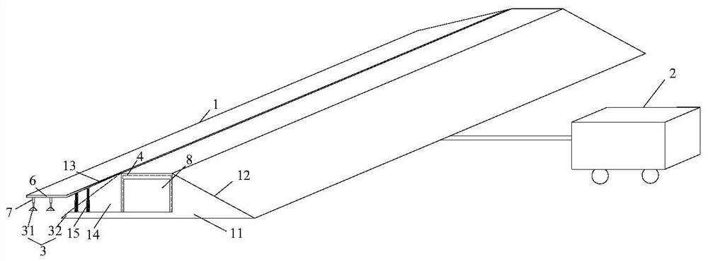
[0039] A kind of road bridge deicing machine provided by the present invention comprises:

[0040] The arch bridge structure 1 is used to meet the normal traffic of vehicles while deicing;

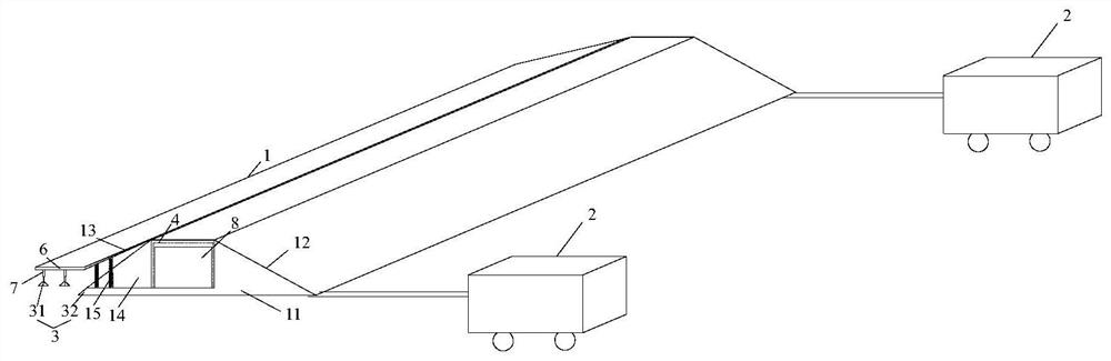
[0041] The moving mechanism 2 is used to make the arch bridge structure move along the length direction of the road bridge;

[0042] The deicing mechanism 3 is used to remove ice and snow on the road surface;

[0043] Described arch bridge structure 1 comprises:

[0044] support body 11;

[0045] The upslope surface 12 is fixed on the supporting body 11 parallel to the width direction of the road bridge;

[0046] Downslope 13, the top of which is hinged on the opposite side of support body 11 to upslope 12;

[0047] The accommodating cavity 14 is arranged in the supporting body 11, and the side close to the downhill surface 13 is an open end;

[0048] The first elastic support member 15 is arranged between the downslope surface 13 and the bottom of the accommodation chamber 14, and th...

Embodiment 2

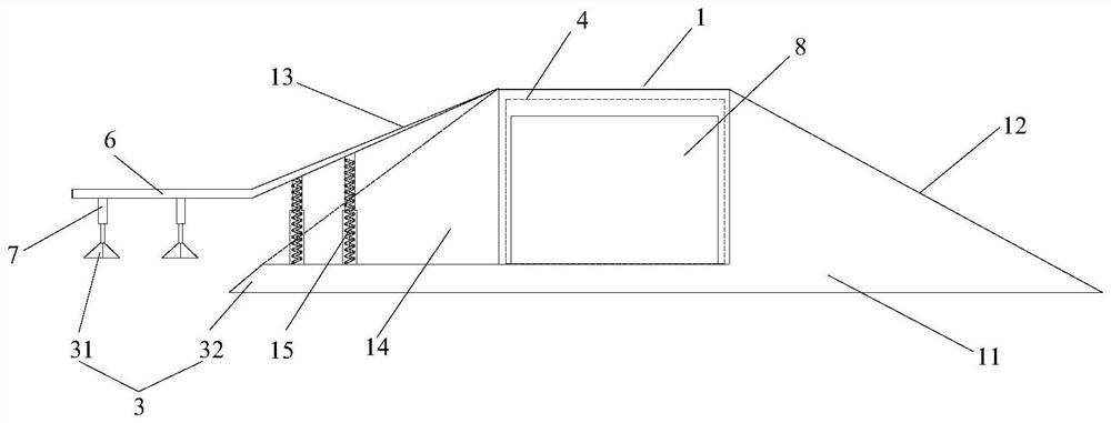
[0054] The deicing mechanism 3 includes:

[0055] The crampons 31 are arranged at the bottom of the downhill surface 13 close to the ground;

[0056] The deicing shovel 32 is arranged on the outer edge of the supporting body 11 close to the downhill surface 13 , and is used for shoveling the ice cubes broken by the crampons 31 and storing them in the receiving chamber 14 .

[0057] The deicing mechanism 3 of this embodiment can realize efficient deicing by combining ice breaking and ice shoveling.

Embodiment 3

[0059] An ice pusher 4 is provided inside the accommodation chamber 14 of this embodiment, and the ice pusher 4 is connected with a driving device 5 for driving the ice pusher 4 to reciprocate. Outlet 8 for ice cube discharge.

[0060]When working, the ice-breaking claws 31 break the ice in front, which can destroy the structure of the ice layer, increase the friction between the de-icing blade 32 and the ice surface, and improve the ice-shoveling efficiency. The crushed ice will be received into the accommodation chamber 14, and will be discharged through the outlet 8 when the crushed ice accumulates a lot.


PUM


Abstract

The invention discloses a road and bridge deicing machine, which belongs to the technical field of deicing equipment. The deicing machine includes: the arch bridge structure is used to meet the normal traffic of vehicles while deicing; the moving mechanism is used to make the arch bridge structure move along the length direction of the road bridge; the deicing mechanism is used to remove ice and snow on the road; the arch bridge The structure includes: a supporting body; an upslope surface, fixed on the support body parallel to the width direction of the road bridge; a downslope surface, the top of which is hinged on the opposite side of the support body to the upslope surface; an accommodating cavity, arranged in the support body , and the side close to the downslope is an open end; the first elastic support is arranged between the downslope and the bottom of the accommodation chamber, and the bottom of the first elastic support is fixed on the bottom of the accommodation chamber for The downhill surface is elastically supported; the deicing mechanism is arranged at the outer edge of the bottom of the accommodation chamber parallel to the road surface. The deicing machine of the present invention can carry out traffic and deicing at the same time, has high deicing efficiency, and has little damage to the road surface.

Description

technical field [0001] The invention relates to the technical field of deicing equipment, in particular to a deicing machine for roads and bridges. Background technique [0002] In the cold winter, the road surface is frozen due to snowfall, which will have a serious adverse effect on the smoothness of the road and driving safety. [0003] At present, there are certain defects in the deicing technology of roads and bridges. The method of sprinkling salt and melting ice has caused serious damage to road surfaces, bridges and the environment, causing serious economic losses. Thermal snow-melting deicing technology melts ice and snow quickly, is safe and environmentally friendly, but it consumes a lot of energy, costs high, and the process is complicated. In addition, this technology has special requirements for the applied pavement materials, structure and construction, and the later maintenance costs are high; [0004] Mechanical deicing, mostly using ordinary hammering and ...

Claims


Application Information

Patent Timeline
Patent Type & Authority Patents(China)
IPC IPC(8): E01H5/10
CPCE01H5/104
Inventor 尹亮闫海奇赵宝俊杨永恒藏斌赵鹏文家岗吴迪
Owner 陕西交通控股集团有限公司
Why Eureka
Try Eureka