
Radial guide

A technology of guides and components, applied in the direction of engine components, valve casing structures, valve operation/release devices, etc., can solve problems such as large tolerance ranges

Pending Publication Date: 2020-10-30
MINEBEA CO LTD
View PDF1 Cites 0 Cited by
  • Summary
  • Abstract
  • Description
  • Claims
  • Application Information

AI Technical Summary

Problems solved by technology

But this component usually has a larger tolerance range in practice, so a firm setting of the radial guide cannot be ensured in all cases

Method used


Image

  • Radial guide
  • Radial guide
  • Radial guide

Examples


Embodiment Construction

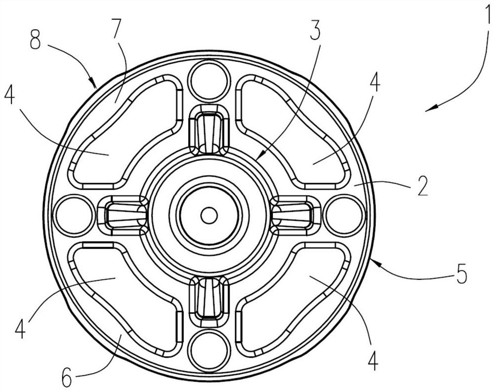
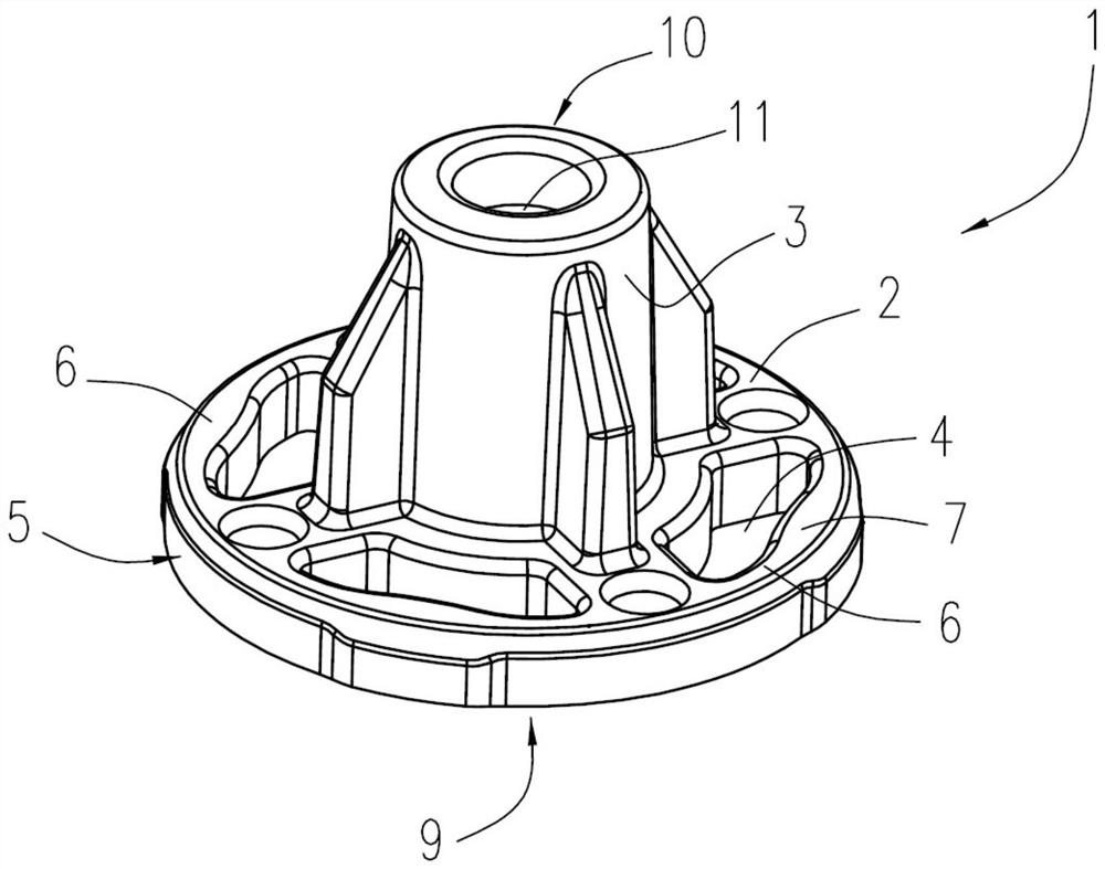
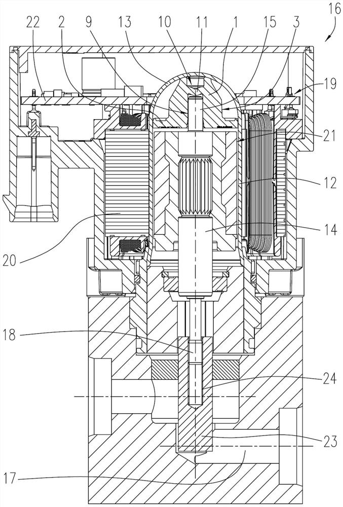
[0020] figure 1 A top view of an exemplary radial guide 1 according to the invention is shown. The radial guide 1 has a circular disc-shaped part 2 and a cylindrical part 3 . The cylindrical part 3 is arranged centrally, in particular centrally, with respect to the disk part 2 . The cylindrical portion 3 forms a housing for a component (not shown). The disc 2 comprises an opening 4 forming a notch. Through the opening 4 , an elastic connecting piece 6 is formed along the circumference 5 of the disk 2 . The elastic connecting piece 6 forms a radial spring. The openings 4 and the elastic connecting pieces 6 are evenly distributed along the circumference 5 . The openings 4 have the same contour. Each quadrant of the circular disk 2 has an opening 4 of the same contour. As a result, radial spring elements (elastic webs 6 ) of the same type are formed uniformly distributed along the circumference 5 . The elastic web 6 has a radially extending thickening or widening 7 in its...


PUM


Abstract

The invention relates to a radial guide having a disk in which an opening is provided, and a cylindrical part which is arranged substantially centrally with respect to the disk,through an elastic webfor receiving a radial force is formed through the opening formed in the disk.

Description

technical field [0001] The invention relates to a radial guide. Background technique [0002] In mass-produced components and / or components that have to be produced inexpensively, the radial guide is a cost-effective alternative to plain bearings. In order to be able to act as a guide, the radial guide must be positionable axially as well as radially. In order to ensure a firm setting of the radial guides, the members holding the radial guides must be manufactured precisely. In practice, however, this component generally has a larger tolerance range, so that a secure arrangement of the radial guide cannot be ensured in all cases. Contents of the invention [0003] It is an object of the present invention to provide a radial guide with better axial positioning on a cylindrical surface with a greater tolerance range, in particular on the inner surface of a hollow cylinder. [0004] This object is achieved by the invention as presented in the independent claims. Preferred...

Claims


Application Information

Patent Timeline
IPC IPC(8): F16C27/02
CPCF16C27/02F16C2361/91F16K27/08F16K31/04F16K31/508F16K27/029F16C17/02F16C23/04
Inventor D·尼克
Owner MINEBEA CO LTD
Learn More