Shaft and bearing matching structure

A kind of bearing cooperation, bearing technology, is used in the direction of bearing and bearings, bearing components, and rigid brackets of bearing components.

Active Publication Date: 2019-06-21
WANXIANGQIANCHAO CO LTD +1
View PDF6 Cites 0 Cited by
  • Summary
  • Abstract
  • Description
  • Claims
  • Application Information

AI Technical Summary

Problems solved by technology

Because the groove coming out of the car will cause local uneven force, stress concentration, and cracks are prone to occur in the groove

Method used


Image

  • Shaft and bearing matching structure

Examples


Embodiment Construction

[0020] The present invention will be further described below in conjunction with the accompanying drawings and specific embodiments.

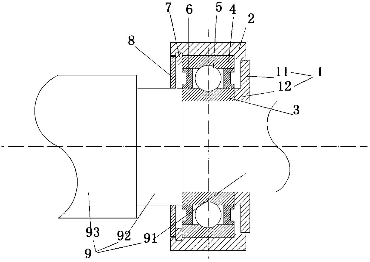
[0021] like figure 1 As shown, a shaft and bearing matching structure, including

[0022] A shaft and bearing matching structure, comprising a long-handle three-column groove shell rod part 9, a bearing support 2, a pressure ring 1 and a bearing fixed on the bearing support 2, the long-handle three-column groove shell rod part 9 Including the first shaft rod 91, the shoulder portion 92 and the main shaft rod 93 connected in sequence, the bearing includes the bearing inner ring 3, the bearing outer ring 4, several rollers 5 and the bearing sealing ring 6, the bearing inner ring 3 is sleeved on the outside of the first shaft 91 and the bearing inner ring 3 is fixed to the first shaft 91, the pressure ring 1 is sleeved on the outside of the first shaft 91 and the pressure ring 1 is connected to the first shaft 91 A shaft 91 is fixed, the pressur...


PUM


Abstract

The invention discloses a shaft and bearing matching structure for axially positioning a bearing on a shaft or a rod without a groove. The shaft and bearing matching structure comprises a long-handlethree-column-groove shell rod part, a bearing support, the bearing and a pressing ring, wherein the bearing is fixed on the bearing support; the bearing comprises a bearing inner ring, a bearing outerring, a plurality of rollers and a bearing sealing ring, the bearing is arranged on the long-handle three-column-groove shell rod part in a sleeve mode, the pressing ring is arranged on the long-handle three-column-groove shell rod part in a sleeve mode, and the pressing ring is fixed on one side of the bearing; and the inner side wall of the pressing ring is in interference fit with the long-handle three-column-groove shell rod part, and the pressing ring carries out axial positioning on one side of the bearing. Due to the fact that the long-handle three-column-groove shell rod part is freeof the groove, the problem of concentrated stress is avoided, and the risk of generating cracks during torsional fatigue is reduced; and compared with an axial positioning structure adding an limitingbaffle ring to the groove, the axial positioning effect of the shaft and bearing matching structure is better.

Description

technical field [0001] The invention relates to the field of constant-velocity drive shafts of automobiles, in particular to a shaft-bearing matching structure. Background technique [0002] When it is necessary to install bearings and bearing supports on the rod part of the long handle three-column groove shell of the existing automobile constant velocity drive shaft or other shaft parts, a groove is generally formed on the rod part or the shaft, and a limit valve is installed in the groove. The retaining ring is used to limit the axial position of the bearing, and at the same time, the retaining ring needs to be pressed to prevent mud, water, dust, etc. from entering the bearing. In order to install the bearing, it is also necessary to carve a groove on the shaft or the rod, which increases the process and reduces the work efficiency. Because there is a groove on the shaft or the shaft, the stress concentration at the groove will be caused during the heat treatment or str...

Claims


Application Information

Patent Timeline
Patent Type & Authority Applications(China)
IPC IPC(8): F16C3/02F16C35/063F16C33/78F16H57/021
Inventor 赵杰颜杭奇林文武郑德信
Owner WANXIANGQIANCHAO CO LTD
Why Eureka
Try Eureka