
Air duct structure of air conditioner and air conditioner comprising same

A technology of air conditioner and air guiding structure, which is applied in the direction of air conditioning system, space heating and ventilation, home appliances, etc., and can solve the problem of reduced air supply distance at the bottom, irregular component structure, placement position, and reduced air volume and wind speed at the bottom. Small and other problems, to achieve the effect of increasing air volume and wind speed, improving user experience, and improving the effect of wind output

Pending Publication Date: 2020-10-30
GREE ELECTRIC APPLIANCES INC OF ZHUHAI
View PDF0 Cites 0 Cited by
  • Summary
  • Abstract
  • Description
  • Claims
  • Application Information

AI Technical Summary

Problems solved by technology

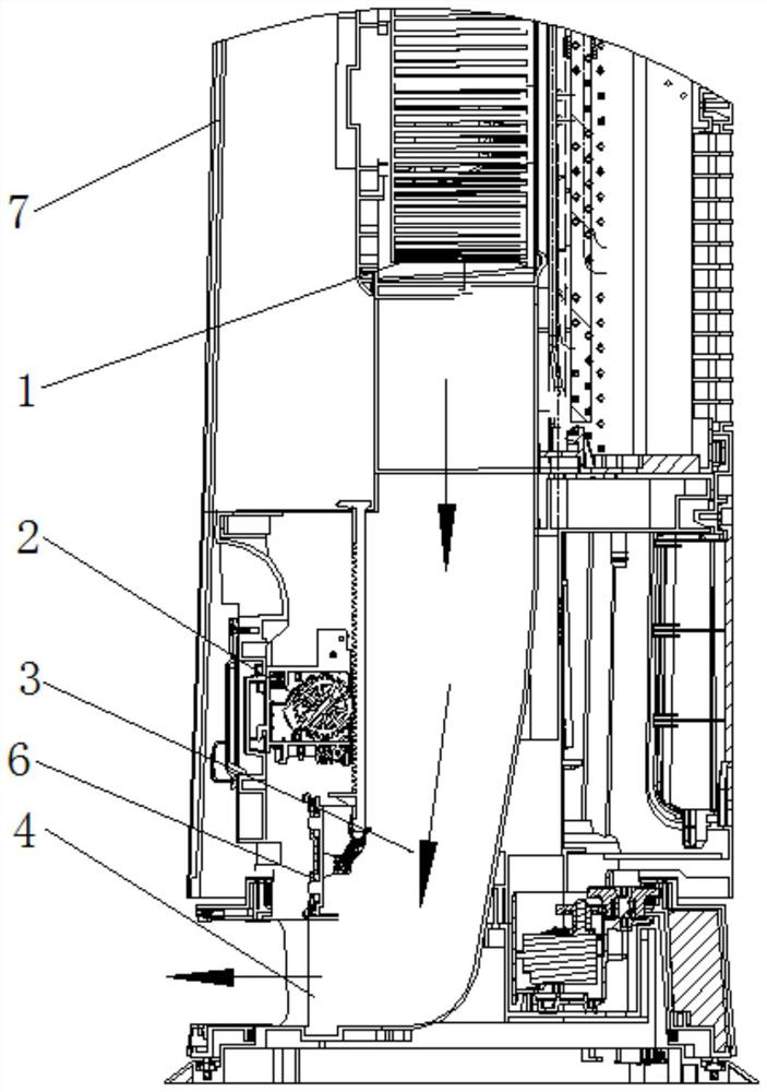
However, because the air outlet door 6 and its control device 2 are all arranged in the air duct 3, and the control device 2 has many structural components, and the structure and placement of the components are irregular, so that the air from the bottom passes through the air outlet door 6 and its control device 2 When the vortex is generated, the air volume and wind speed of the bottom air outlet will be greatly reduced and reduced, resulting in a reduction in the bottom air supply distance, affecting the effect of the bottom air outlet, and thus affecting the experience of the whole machine

Method used


Image

  • Air duct structure of air conditioner and air conditioner comprising same
  • Air duct structure of air conditioner and air conditioner comprising same
  • Air duct structure of air conditioner and air conditioner comprising same

Examples


Embodiment Construction

[0036] The technical solutions of the present invention will be clearly and completely described below in conjunction with the accompanying drawings. Obviously, the described embodiments are part of the embodiments of the present invention, rather than all of the embodiments. Based on the embodiments of the present invention, all other embodiments obtained by those of ordinary skill in the art without creative work shall fall within the protection scope of the present invention.

[0037] In addition, the technical features involved in the different embodiments of the present invention described below can be combined with each other as long as they do not conflict with each other.

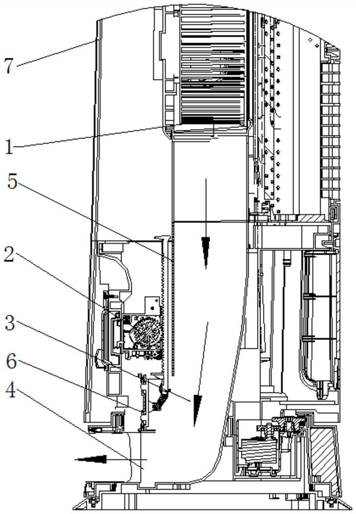
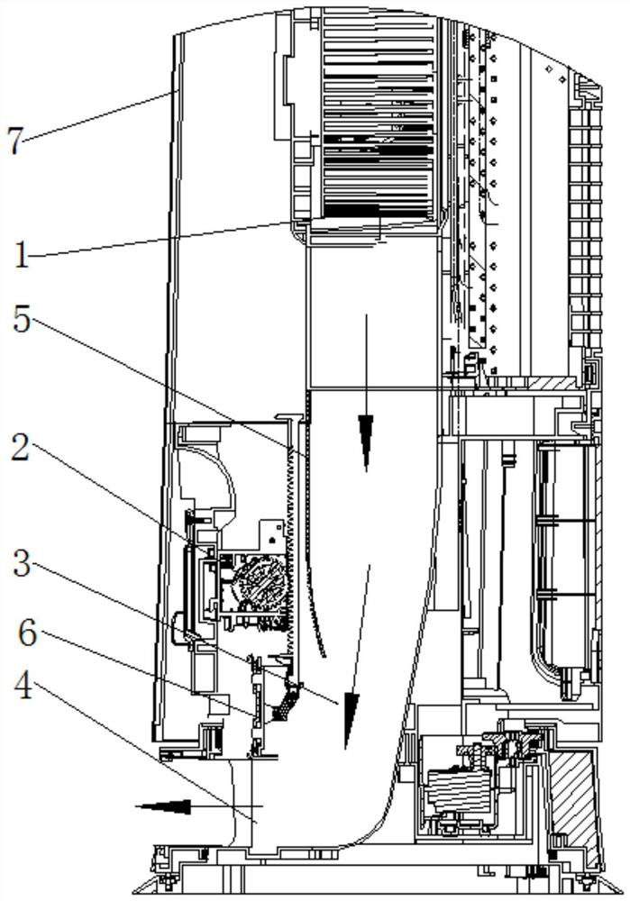
[0038] Such as Figure 2-Figure 4 As shown, this embodiment provides an air duct structure of an air conditioner, which includes: an air outlet cavity, an air outlet door 6, a control device 2 and an air guide structure 5.

[0039] The air outlet cavity is connected with at least one air outlet 4; the air...


PUM


Abstract

The invention relates to the technical field of air conditioners, in particular to an air duct structure of an air conditioner and the air conditioner comprising the same. The air duct structure of the air conditioner comprises an air outlet cavity, an air outlet door, a control device and an air guide structure, wherein the air outlet cavity communicates with at least one air outlet; the air outlet door is arranged in the air outlet cavity and is suitable for opening or closing the air outlet; the control device is arranged in the air outlet cavity and is suitable for controlling the air outlet door to open or close the air outlet; and the air guide structure is arranged in the air outlet cavity and divides the air outlet cavity into a control cavity internally provided with the control device and an air duct communicating with the air outlet and a fan. The air guide structure is arranged in the air outlet cavity and divides the air guide structure into the control cavity and the airduct, so that air discharged from the fan passes through the air duct as far as possible and is blown out from the air outlet, and air blown to the control device is reduced. Vortexes formed by blowing the air discharged from the fan to the control device are reduced. The air outlet capacity and the air speed are increased. The air supply distance is lengthened. The air outlet effect is improved.

Description

Technical field [0001] The invention relates to the technical field of air conditioners, in particular to an air duct structure of an air conditioner and an air conditioner having the same. Background technique [0002] With the development of the air conditioning industry, the design of the circular cabinet air conditioner structure pays more attention to appearance and practical experience. In order to improve user comfort, the circular cabinets in the prior art mostly adopt upper and lower air outlet designs, and the functional form can be realized: simultaneous air outlet from top to bottom, independent air outlet from the upper part, and independent air outlet from the bottom. [0003] Such as figure 1 As shown, the control of the bottom air outlet function mostly adopts an air outlet 6 and its control device 2 inside the air duct 3 of the bottom air outlet 4, and the air outlet 6 is controlled by the control device 2 to slide to the bottom air outlet 4 to close the bottom air...

Claims


Application Information

Patent Timeline
IPC IPC(8): F24F13/08F24F1/0011
CPCF24F1/0011F24F13/08
Inventor 蔡金钊程春雨王千千陈荣华杨登明刘雷明
Owner GREE ELECTRIC APPLIANCES INC OF ZHUHAI
Learn More