A rubber glove inspection device
A technology of rubber gloves and inspection devices, which is applied in the direction of measuring devices, testing of machine/structural components, instruments, etc., can solve the problems of workers' sore hands and achieve the effect of inspection
- Summary
- Abstract
- Description
- Claims
- Application Information
AI Technical Summary
Problems solved by technology
Method used
Image

Examples
Embodiment 1
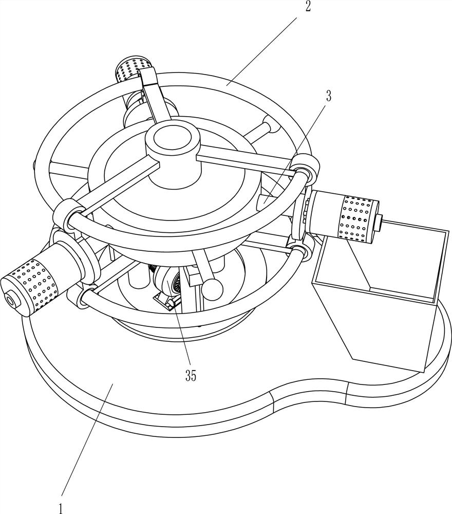
[0032] A rubber glove inspection device such as figure 1 As shown, it includes a base 1 , a rotating mechanism 2 and an air blowing mechanism 3 , the base 1 is provided with a rotating mechanism 2 , and parts of the rotating mechanism 2 and the base 1 are equipped with an air blowing mechanism 3 .
[0033] When it is necessary to check the rubber gloves, manually put the rubber gloves on the parts of the blowing mechanism 3, place the collection frame on the right side of the base 1, then start the parts of the blowing mechanism 3, manually turn the parts of the rotating mechanism 2 clockwise, When the rubber glove is facing the parts of the blowing mechanism 3, manually stop rotating the parts of the rotating mechanism 2 and fix the rubber glove, the wind generated by the parts of the blowing mechanism 3 then enters the rubber glove, and the rubber glove is checked. After the rubber glove has been inspected, continue to manually rotate the parts of the rotating mechanism 2 so...
Embodiment 2
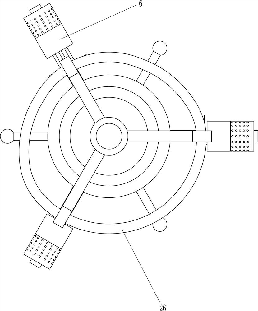
[0035] Specifically, such as Figure 1-3 , the rotating mechanism 2 includes a support column 21, a round platform 22, a circular ring 23, a cylinder 24, a connecting rod 25, a slip ring 26 and a handle 27, three support columns 21 are installed on the left side of the top of the base 1, and a round platform is arranged on the top of the support column 21 22. The outer sliding sleeve of the round platform 22 is provided with a circular ring 23, and the top and bottom center of the round platform 22 are provided with a cylinder 24, and three connecting rods 25 are evenly arranged on the outer wall of the cylinder 24, and the outer ends of the three connecting rods 25 are installed. A slip ring 26 is arranged, and a handle 27 is evenly connected on the outer wall of the circular ring 23 .
[0036] After manually starting the parts of the blowing mechanism 3, hold the handle 27 and turn clockwise, the parts of the ring 23 and the blowing mechanism 3 rotate thereupon, and the part...
Embodiment 3
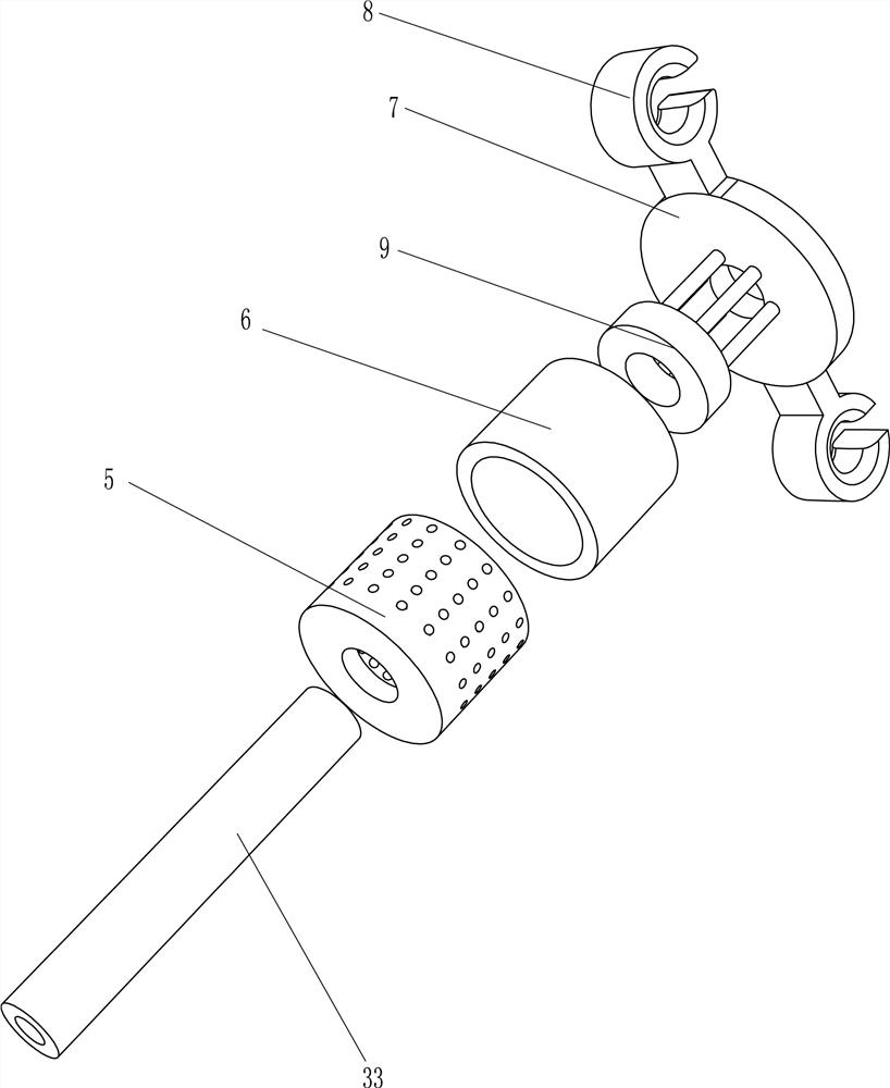
[0040] refer to Figure 2-5 As shown in the diagram, it also includes an adsorption cylinder 5, a compression cylinder 6, a disk 7, a first slider 8 and a piston 9. The right part of the round table 22 is provided with a third air hole 4, and the first air hole 4 on the side away from the round table 22 is The air pipe 33 is provided with an adsorption cylinder 5, the first air pipe 33 is equipped with a compression cylinder 6, the compression cylinder 6 is located between the adsorption cylinder 5 and the ring 23, the first air pipe 33 is provided with a disc 7, the disc 7 Both the top and the bottom are connected with a first slider 8, the first slider 8 is slidably located on the slip ring 26, the first slider 8 is in contact with the connecting rod 25, a piston 9 is installed in the compression cylinder 6, and the piston 9 and the disc 7 side connections.
[0041]Manually put rubber gloves on the adsorption cylinder 5, then start the air jet 35, turn the handle 27 clockwi...
PUM
 Abstract
Description
Claims
Application Information
 - R&D
- Intellectual Property
- Life Sciences
- Materials
- Tech Scout
- Unparalleled Data Quality
- Higher Quality Content
- 60% Fewer Hallucinations
Browse by: Latest US Patents, China's latest patents, Technical Efficacy Thesaurus, Application Domain, Technology Topic, Popular Technical Reports.
© 2025 PatSnap. All rights reserved.Legal|Privacy policy|Modern Slavery Act Transparency Statement|Sitemap|About US| Contact US: help@patsnap.com