Eureka AIR delivers breakthrough ideas for toughest innovation challenges, trusted by R&D personnel around the world.

Method for changing electromagnetic interference coupling path of ignition coil

An electromagnetic interference, coupling path technology, applied in circuits, preventing/reducing unwanted electromagnetic/magnetic effects, transformers, etc., can solve problems such as unfavorable stable combined installation, unfavorable normal coupling, large capacitance structure, etc., to improve convenience performance and stability, reduce electromagnetic feedback, and facilitate installation and fixation

Active Publication Date: 2020-10-30
浙江辉波蕾汽车部件有限公司
View PDF4 Cites 0 Cited by
  • Summary
  • Abstract
  • Description
  • Claims
  • Application Information

AI Technical Summary

Problems solved by technology

[0003] However, in the existing electromagnetic interference protection structures, most of the shielding structures are directly installed on the capacitors connected by the two coils. This will not only cause the structure of the capacitors to be too large, which is not conducive to the arrangement, but also not conducive to stable combination installation, resulting in misalignment. It is not conducive to normal coupling and needs to be improved

Method used


Image

  • Method for changing electromagnetic interference coupling path of ignition coil
  • Method for changing electromagnetic interference coupling path of ignition coil

Examples


Embodiment

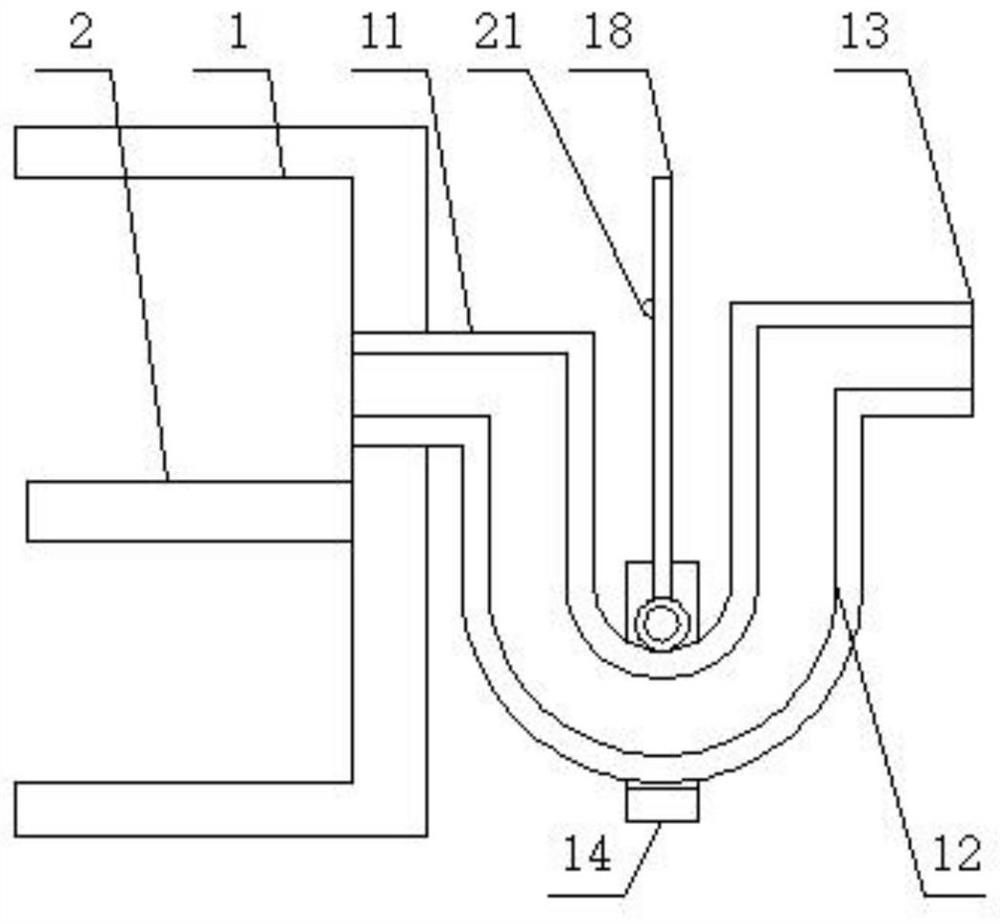
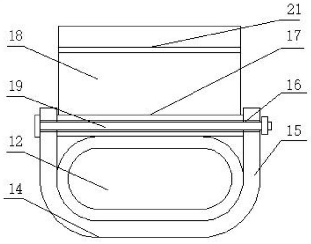
[0024] see figure 1 with figure 2 , a method for changing the electromagnetic interference coupling path of an ignition coil, comprising a U-shaped baffle 1, one side surface of the U-shaped baffle 1 is fixedly connected with a connecting pipe 11, and the other end of the connecting pipe 11 is fixedly connected with an arc hollow pipe 12 , the other end of the arc hollow tube 12 is fixedly connected with a right-angle coupling tube 13, which is welded in one piece, which is convenient for combined installation and use, and is changed into an arc path, which can reduce electromagnetic transmission and improve the anti-interference effect. One side of the arc hollow tube 12 A U-shaped fixed block 14 is fixedly installed on the surface, and both sides of the U-shaped fixed block 14 are provided with a fixed plate 15. The surface of the fixed plate 15 is provided with an installation through hole 16, and the other side surface of the fixed plate 15 is fixedly connected with a hor...


PUM


Abstract

The invention discloses a method for changing an electromagnetic interference coupling path of an ignition coil. A U-shaped baffle is arranged, and a connecting pipe is fixedly connected to the surface of one side of the U-shaped baffle; the other end of the connecting pipe is fixedly connected with an arc hollow pipe; the other end of the arc hollow pipe is fixedly connected with a right-angle coupling pipe; a U-shaped fixing block is fixedly mounted on the surface of one side of the arc hollow pipe; fixing plates are arranged on the two sides of the U-shaped fixing block, mounting through holes are formed in the surfaces of the fixing plates; the surfaces of the other sides of the fixing plates are fixedly connected with transverse cylinders; shielding plates are fixedly connected to theside faces of the transverse cylinders, the surfaces of the shielding plates are located on one side of the U-shaped baffle, and a coil iron core is fixedly connected to the surface of the other sideof the U-shaped baffle, so that the use convenience and stability can be greatly improved, and the anti-interference effect is guaranteed.

Description

technical field [0001] The invention relates to the technical field of ignition coils, in particular to a method for changing an electromagnetic interference coupling path of an ignition coil. Background technique [0002] During the use of the ignition coil, due to the structural arrangement and its own ignition characteristics, electromagnetic interference will be generated and affect the normal operation of other components. In order to ensure safety and stability, protection is required. [0003] However, in the existing electromagnetic interference protection structures, the shielding structure is directly installed on the capacitor connected by the two coils, which will not only cause the structure of the capacitor to be too large, which is not conducive to the arrangement, but also not conducive to the stable combination installation, resulting in misalignment After that, it is not conducive to normal coupling and needs to be improved. Contents of the invention [...

Claims


Application Information

Patent Timeline
IPC IPC(8): H01F38/12H01F27/36
CPCH01F38/12
Inventor 刘周翔周振辉
Owner 浙江辉波蕾汽车部件有限公司
Why Eureka
Eureka Blog
Learn More