Wire harness

A wire harness and trunk line technology, applied in the field of wire harnesses, to prevent interference, improve layout operability, and prevent damage and breakage

Active Publication Date: 2020-10-30
YAZAKI CORP +1
View PDF14 Cites 0 Cited by
  • Summary
  • Abstract
  • Description
  • Claims
  • Application Information

AI Technical Summary

Problems solved by technology

In addition, assuming that the length of the harness main line 4 shown in the figure is formed on the positive side of the dimensional tolerance (if it is long), since the bent portion 11 becomes large, the above-mentioned deviation is likely to occur as a result.

Method used


Image

  • Wire harness
  • Wire harness
  • Wire harness

Examples


Embodiment

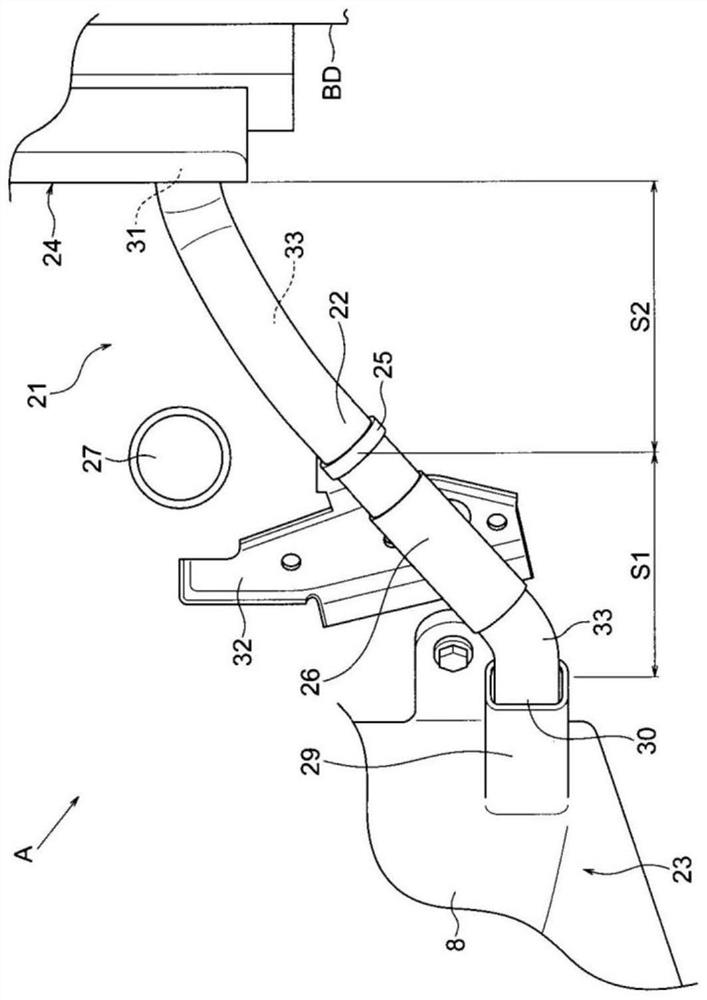
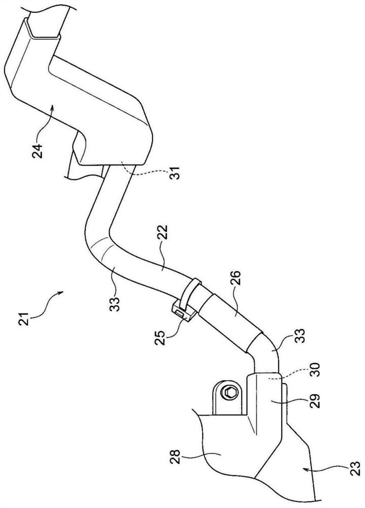
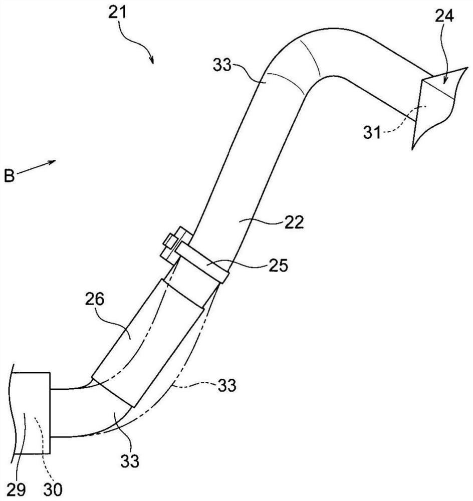
[0046] Hereinafter, an embodiment will be described with reference to the drawings. figure 1 It is a perspective view which shows one Embodiment of the wire harness of this invention. in addition, figure 2 From figure 1 The perspective view of the wire harness viewed in the direction of the arrow A, image 3 is a perspective view of the harness trunk, Figure 4 From image 3 A perspective view of the trunk line of the harness viewed in the direction of arrow B.

[0047] (About Harness 21)

[0048] exist figure 1 and figure 2 In this example, the wire harness 21 arranged in the engine room of the automobile will be described as an example. The wire harness 21 is drawn out from the engine room and used for electrical connection between devices. figure 1 and figure 2 The wire harness 21 of the shown range is provided with: a wire harness trunk line 22, a relay box 23 (an example of an electrical connection box, a device) provided at the end of the wire harness tr...


PUM


Abstract

The invention provides a wire harness capable of suppressing deviation of an arrangement state and preventing interference. The wire harness (21) is provided with a wire harness trunk line (22) and arotating jig (25). The wire harness main line (22) passes through a wire harness lead-out portion (29) of the electrical connection box and a protector (24) fixed away from the electrical connection box and is arranged between the wire harness lead-out portion and the protector. The rotary clamp (25) is arranged in the middle of the wire harness main line (22). The wire harness main line (22) is provided with bendable bent parts (33) in a first section (S1) between the first fixed part (30) and the rotary clamp (25) and a second section (S2) between the second fixed part (31) and the rotary clamp (25). In addition, the wire harness trunk line (22) is formed in an arrangement shape bent substantially in an S-shape as a whole from the first fixing part (30) to the second fixing part (31). Inaddition, the wire harness trunk line (22) is provided with a hard pipe (26) (hard part) which is harder than the bent part (33) and is approximately linear in shape in the first section (S1).

Description

technical field [0001] The present invention relates to a wire harness arranged at a predetermined position of an automobile. Background technique [0002] For example, a battery, an alternator, a relay box, and the like are mounted in an engine room of an automobile. The output terminals of the battery and the output terminals of the alternator are connected to the relay box. Then, the relay box and the relay box are also connected to a junction box in the vehicle interior via a wire harness provided at the end (see, for example, Patent Document 1 below). [0003] prior art literature [0004] patent documents [0005] Patent Document 1: Japanese Unexamined Patent Publication No. 2014-97709 [0006] Taking the above-mentioned relay box and wiring harness as an example, the wiring harness is generally bent into a three-dimensional shape for arrangement. refer to Figure 5 and Figure 6 Specifically, reference numeral 1 denotes a relay box (electrical connection box), r...

Claims


Application Information

Patent Timeline
Patent Type & Authority Applications(China)
IPC IPC(8): H02G3/30H02G3/32H02G3/06H02G3/34B60R16/02
CPCH02G3/30H02G3/32H02G3/0616H02G3/34B60R16/0215
Inventor 日浅贵裕池田一弘云井一行松本贤太稻垣喜仙高村修平
Owner YAZAKI CORP
Why Eureka
Try Eureka